
Instruction Manual

EN - English - Instructions manual
18
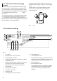
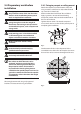
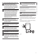
Inside the junction box you'll nd an address
and protocol board and a connectors board with
removable connectors that make the cabling
procedure easy.
F
U
S
E
F
U
S
E
100nMBW3
L
N
VAR3
VAR1
AC
AL1
AL2
AL3
AL4
AL5
COM
RL1
RL1
RL2
RL2
GND
W
GND
B
A
B
A
IN
J1
J6
J2
J3
J8
J7
FUS1
VAR2
VIDEO - 1
VIDEO - 2
RS485
FUS2
J9
Fig. 13
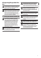
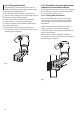
6.1.4 Cable entry
Only MPXT series have 2 coax cable video
output.
To prevent the passage of ames or explosions from
the unit to the conduit system or cable gland to the
external environment, use connection in conformity
with IEC/EN60079-14.
All cable gland devices shall be certied in type of
explosion protection “d” and/or "tb", suitable for the
conditions of use and correctly installed.
When conduit is used, a suitable certied stopping
box, in type of explosion protection “d” and/or "tb",
suitable for the conditions of use and correctly
installed. Being tted within 25mm (1in) from the
enclosure wall.
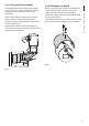
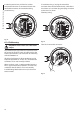
To make the wirings, unplug the removable
connector from the connection board, cable all the
conductors on it and then plug the ying connector
on the board as shown.
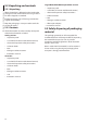
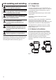
Telemetry wiring.
F
U
S
E
F
U
S
E
100nMBW3
L
N
VAR3
VAR1
AC
AL1
AL2
AL3
AL4
AL5
COM
RL1
RL1
RL2
RL2
GND
W
GND
B
A
B
A
IN
J1
J9
J6
J2
J3
J8
J4
J7
FUS1
VAR2
VIDEO - 1
VIDEO - 2
RS485
ADDRESS & PROTOCOL
FUS2
Fig. 14
Take the J9 removable connector.
F
U
S
E
F
U
S
E
100nMBW3
L
N
VAR3
VAR1
AC
AL1
AL2
AL3
AL4
AL5
COM
RL1
RL1
RL2
RL2
GND
W
GND
B
A
B
A
IN
J1
J9
J6
J2
J3
J8
J4
J7
FUS1
VAR2
VIDEO - 1
VIDEO - 2
RS485
ADDRESS & PROTOCOL
FUS2
Fig. 15