VideoLabs Ceiling DocCamTM ® Installation Instructions & Operator’s Guide 1
VideoLabs Ceiling DocCam Table of Contents Intended Use 3 FCC Statement CE Declaration 3 3 1.0 Unpacking and Getting Started 4 1.1 Contents of Ceiling DocCam Package 4 1.2 First-Time Set Up 4 1.3 Cable Connections 7 1.4 IR Remote Control 9 1.5 RS-232 Remote Control 9 1.6 Care and Cleaning 10 1.7 Operating And Storage Conditions 10 2.0 Troubleshooting 10 3.0 Technical Specifications 11 4.0 Warranty Information 12 5.
INTENDED USE Before operating the Ceiling DocCam, please read the entire manual thoroughly. The VideoLabs Ceiling DocCam was designed, built and tested for use indoors, and with the provided power supply. The use of a power supply other than the one provided or outdoor operation has not been tested and could damage the camera or peripheral equipment and/or create a potentially unsafe operating condition. IMPORTANT SAFEGUARDS 1. Read and understand all instructions before using. 2.
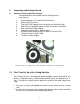
1) Unpacking and Getting Started 1.1 Contents of Ceiling DocCam Package The following items are included with the Ceiling DocCam (see Figure 1): 1. 2. 3. 4. 5. 6. 7. 8. 9.
3. Cut a 3-1/2” diameter round hole into the front side of the ceiling tile centered on the string. It is strongly recommended to score the front of the tile with a sharp utility knife prior to cutting the tile. The camera module bezel (front ring) will fit into the 3-1/2” opening from the rear of the tile (see Figure 2). Figure 2: Side View – Camera Module Enclosure Bezel (front ring) 4.
5. The tile support rails distribute the weight of the camera into the grid and prevent tile warping. The camera module enclosure and the tile support rails allow for exceptional positioning freedom when used with 2’x2’ and 2’x4’ ceiling tiles (Figure 5). Figure 5: Enclosure and Tile Support Braces Positioned on 2’x2’ Ceiling Tile 6. After the camera module enclosure is positioned above the ceiling, attach the white trim ring to the camera module bezel from the front of the tile and tighten gently.
1.3 Cable Connections The camera module enclosure and 50’ connection cable are plenum rated for use inside plenum return air spaces. The connectors on the back of the camera module enclosure are labeled MAIN and RS-232. The enclosure is also equipped with threaded inserts positioned to enable attachment to a standard electrical box (not provided) and with standard conduit connectors (Figure 8).
wall box or placed in an equipment rack in a surface mount wall box. A 12VDC power supply, 25’ S-video cable and a RCA jack to BNC plug adapter are provided for flexibility in connection to video devices (Figures 10, 11 & 12). Figure 10: Power Supply Attached to Front of Wall Plate Plug the 12VDC power supply into a standard wall outlet (110V-120V) and the jack labeled 12 V DC. Use only the power supply provided with the Ceiling DocCam. Use of any unauthorized power supply will void any and all warranties.
1.4 IR Remote Control The IR Remote Control for the Ceiling DocCam requires 2 ‘AAA’ batteries. Pull up the battery cover tab and insert the batteries, making sure the battery +/terminal symbols line up with the +/- symbols on the inside of the battery compartment. The VideoLabs IR Remote controls Power ON/OFF, Zoom-in and Zoom-out. Other IR Remote Controls The Ceiling DocCam can be ordered to respond to the zoom-in and zoom-out commands of the Polycom® ViewStation IR Remote and the PictureTel® IR Keypad.
1.6 1. 2. 3. 4. Care and Cleaning Do not attempt to take the camera apart. There are no user-serviceable components inside. Do not spill liquids onto the camera. Avoid touching the lens. For smears or smudges, clear any dust with a blower and wipe stains with a glass cleaner and clean, soft cloth. To clean exterior of camera, wipe with a clean damp cloth. Do not use any abrasive chemicals. 1.7 Operating and Storage Conditions 1.
3.0 Technical Specifications: Image Pick-up Device Total Pixels No. of Effective Pixels Horizontal Resolution Sensitivity Lens: (Horizontal angle) Mechanical Zoom Digital Zoom Video Output Illumination S/N (min) White Balance Back Light Compensation Iris Shutter Focus Focal Range Current Consumption Control Operating Temperature Weight Dimensions Ceiling Cut-out Trim Ring Wall Plate Cables Power Supply Enclosure ¼ ” CCD 410,000 768H x 494V 470 TV lines 3 lux F1.6 (w)-F3.8 (t) [470 (w)-2.
4.0 Warranty Information on Hardware VideoLabs warrants this product against defects in materials and workmanship for a period of one (1) year from the date of purchase. If VideoLabs receives notice of such defects during the warranty period, VideoLabs will either, at its option, repair or replace products which prove to be defective. Obtaining Warranty Service To obtain warranty service, products must be returned to a service facility designated by VideoLabs.
Shipping and Handling VideoLabs will not pay for inbound shipping, transportation, or insurance charges, or accept any responsibility for loss and/or damage from inbound transit. VideoLabs requires that all overseas returns are shipped via UPS. VideoLabs will pay for outbound shipping, transportation, and insurance charges but will not assume responsibility for loss and/or damage by the outbound freight carrier.
5.0 Quick Connect Guide 1. First connect the 50’ plenum rated, Category 5, RJ-45 plug to RJ-45 plug cable between the RJ-45 jack labeled MAIN on the back of the camera module enclosure and the RJ-45 jack on the back of the provided wall plate. 2. Connect the provided 12VDC power supply to the jack on the front of the plate labeled 12 V DC and plug the power supply into a standard 110V-120V electrical outlet. Use only the provided 12VDC power supply. 3.
Appendix 1 - RS-232C Control Information 1. Communication protocol Communication between the microcomputer of the camera and the PC is available by using the RS-232C protocol. The microcomputer receives each control command given by the PC and echoes it back to the PC. 2. Connect condition Data length Stop bit Parity Baudrate 8 bit 1 bit even 4800 bps 3. Communication data format All communication data consists of eight or ten ASCII characters (8 bytes or 10 bytes).
4. Control commands a) Switch the auto focus / manual focus :RFF0E00 :WFF0EX1X0 bit 3 of X1X0 or :WFCBBA8 :WFCBBFE b) c) d) e) f) : 0-Auto 1-Manual ;Change ;Neutral Move focus to FAR in manual focus mode :WFCBBA9 :WFCBBFE ;Start ;Stop :WFCBBAA :WFCBBFE ;Start ;Stop :WFCBB99 :WFCBBFE ;Start ;Stop :WFCBB9B :WFCBBFE ;Start ;Stop Move focus to NEAR in manual focus mode Move zoom to TELE Move zoom to WIDE Select the zoom speed of optical zoom :RFDFC00 :WFDFCX1X0 Super HIGH SPEED (2.
g) Get the status of zoom position :RFC9100 If echo back data is not “FF”, zoom position is calculated by following equation. zoom position = 22X256/(XX+1) XX; echo back data If echo back data is “FF”, then following commands should be sent. :rF7200000 Echo back data shows zoom position. [Please refer to the attached Table.1.] Table.
l) Switch the auto gain control (AGC) ON/OFF :RFB7F00 :WFB7FX1X0 bit 7 of X1X0 m) Set the fixed AGC level tuning value in AGC OFF mode n) : 0-ON 1-OFF :wFB38X3X2X1X0 X3X2X1X0 : tuning value ( X3X2X1X0=0000~03C0 ; 0.03125dB/step ) [ X3X2X1X0=0000 ; 0dB , X3X2X1X0=03C0 ; 30dB ] Switch the auto / manual white balance :RFBFF00 :WFBFFX1X0 bit 3 of X1X0 : 0-Auto 1-Manual o) Set the white balance (R gain) tuning value in manual white balance mode :wFBBCX3X2X1X0 X3X2X1X0 : tuning value ( min. H’0080, max.
r) Get the luminance data for the 6 screen areas [RAM area] area 1 :RFAE0000000 ; data length 3Byte area 2 :RFAE3000000 ; data length 3Byte area 3 :RFAE6000000 ; data length 3Byte area 4 :RFAE9000000 ; data length 3Byte area 5 :RFAEC000000 ; data length 3Byte area 6 :RFAEF000000 ; data length 3Byte [Note] This is the average data per one field.
v) Set the burst ON/OFF [EEPROM area] * :WE198X1X0 :WE199X1X0 :WE19AX1X0 :WE19BX1X0 ( X1X0=00~FF ; 256 step ) ( X1X0=00~FF ; 256 step ) ( X1X0=00~FF ; 256 step ) ( X1X0=00~FF ; 256 step ) w) Set the chroma suppression level tuning value in AGC range [RAM area] ~ AGC ON :WB790X4Y4 AGC ON ~ 1/3 maximum AGC level :WB791X3Y3 1/3 maximum AGC level ~ 2/3 maximum AGC level :WB792X2Y2 2/3 maximum AGC level ~ maximum AGC level :WB793X1Y1 maximum AGC level ~ :WB794X0Y0 ( X?X?=00~FF ; 256 step ) darker (H’00) < cen
z) Set the vertical aperture level tuning value :WFBF9X1X0 ( X1X0=00~1F ; 32 step ) [EEPROM area] * ~ AGC ON :W13A0X4Y4 AGC ON ~ 1/3 maximum AGC level :W13A1X3Y3 1/3 maximum AGC level ~ 2/3 maximum AGC level :W13A2X2Y2 2/3 maximum AGC level ~ maximum AGC level :W13A3X1Y1 maximum AGC level ~ :W13A4X0Y0 ( X?X?=00~1F ; 32 step ) [Note] maximum AGC level setting at page 15 - item m) vertical aperture level tuning values at Fig.
5. Other useful commands a) Continuous Digital Zoom Control ZOOM OPERATION ZOOM START Get digi. zoom :RFC91XX (XX:MAG) XX=H ’FF? Digi. Zoom on? yes no Optical Zoom area Digital Zoom area no ZOOM TELE? ZOOM TELE? yes TELE no Continuous digi. zoom ON? yes Continuous digi. zoom ON :WFCCB01 yes WIDE Send zoom to tele command :WFCBB99 TELE no Send digi. zoom tele command :WBFBB08 Send zoom to wide command :WFCBB9B no no Zoom stop? Zoom stop? yes yes Send digi.