TMX24120 Label & Location November 6 2012 VIDEOCOMM TECHNOLOGIES (1156488 ONTARIO INC.
TMX24120 Label & Location November 6 2012 FCC REGULATORY COMPLIANCE INTEGRATION AND USE INFORMATION INTEGRATION AND INSTALLATION REQUIREMENTS The TMX24120 RADIO MODULE is designed exclusively for use in the VideoComm RTWave family of wireless video systems. The TMX24120 RADIO MODULE will not function in any other system.
TMX24120 Label & Location November 6 2012 INDUSTRY CANADA REGULATORY COMPLIANCE INTEGRATION AND USE INFORMATION INTEGRATION AND INSTALLATION REQUIREMENTS This device complies with Industry Canada license-exempt RSS standard(s). Operation is subject to the following two conditions: (1) this device may not cause interference, and (2) this device must accept any interference, including interference that may cause undesired operation of the device.
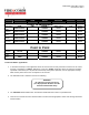
TMX24120 Label & Location November 6 2012 MODEL # ANTENNA TYPE ANTENNA GAIN FREQUENCY RANGE SEPARATION DISTANCE Cable Loss RUB-2400 RUB243RPS RUB243S RUB5824S ANT2412OD OMNIDIRECTIONAL OMNIDIRECTIONAL OMNIDIRECTIONAL OMNIDIRECTIONAL OMNIDIRECTIONAL 40cm or 15.7 Inches 40cm or 15.7 Inches 40cm or 15.7 Inches 40cm or 15.7 Inches 40cm or 15.7 Inches 1.31 ANT2415DP DIRECTIONAL PATCH 20.5dBi 2400MHz – 2483MHz 40cm or 15.7 Inches 2.
TMX24120 Label & Location November 6 2012 5. If the FCC ID for the TMX24120 Radio is not visible when installed in the host platform, then a permanently attached or marked label must be displayed on the host unit referring to the enclosed radio. 6. For example, the label should contain wording such as: Contains: TMX24120 Radio transmitter module FCC ID: SU5-TMX24120 / IC : 3667A-TMX24120 This device complies with Part 15 of the FCC Rules.
TMX24120 Label & Location November 6 2012 PROFESSIONAL INSTALLATION The TMX24120 RADIO MODULE will be installed into its system only by VideoComm. The system once assembled will be knows as 2.4GHz Frequency Hopping Spread Spectrum (FHSS) (family of products) The 2.4GHz Frequency Hopping Spread Spectrum (FHSS) (family of products) wireless systems are designed and marketed for professional installation.
TMX24120 Label & Location November 6 2012 TMX24120 MODULE INSTALLATION INSTRUCTIONS The TMX24120 radio will be packaged in a pink anti-static plastic bag. It is critical that it only be opened at an ESD safe work station and the technician be properly instructed on how to handle ESD devices and be grounded with an approved tested wrist strap. The Module will be accompanied by a MASTER BUILD SHEET when removed from inventory and given to a technician for assembly into a SYSTEM.
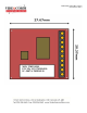
TMX24120 Label & Location November 6 2012 Installation is as follows: 1. First attach the 2 sided foam tape within the marked area on the PCB shown on the master build sheet. Trial fit the radio module on the PCB and ensure it locks in place. (Adjust the PCI fingers to ensure a good fit if needed). Release the Radio and peel off the 2nd protective layer of the 2 sided tape and install the RADIO MODULE (press to make good contact with the tape). 2.
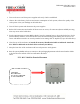
TMX24120 Label & Location November 6 2012 M/N: TMX24120 FCC ID: SU5-TMX24120 IC: 3667A-TMX24120
TMX24120 Label & Location November 6 2012 1. Turn on the server and client power supplies and verify a link is established. 2. Observe the video latency, link rate and current consumption of each system; observe the quality of the video picture. Note your findings on the build sheet. 3. Turn off the 2 systems and disconnect the power supplies 4. Recheck all connections and confirm all loose wires are secure, all connectors (Power and RF) are snug. Note any errors on the build sheet. 5.