
User's Manual

Using the three dipswitches select the
desired channel frequency. Be sure to set
the transmitter and receiver on the same
channel.
Please see dipswitch channel settings
attached.
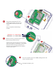
NEGATIVE ( - ) 9 – 14VDC INPUT
Inside the enclosure you will find a green terminal
strip with orange terminal lock tabs.
Push down the orange lock tabs to open the terminal
input. Insert negative (-) and positive (+) wire leads as
illustrated. Release the orange terminal lock tab.
Ensure the wire is locked tight into the terminal to
avoid an electrical short.
POSITIVE (+) 9 – 14VDC INPUT
Power the transmitter and receiver to ON by sliding the ON / OFF
switch to the down position.
LED light will indicate power