VE.
Copyrights © 2007 Victron Energy B.V. All Rights Reserved This publication or parts thereof, may not be reproduced in any form, by any method, for any purpose. For conditions of use and permission to use this manual for publication in other than the English language, contact Victron Energy B.V. VICTRON ENERGY B.V.
VE.Net GMDSS Panel INSTALLATION AND USER MANUAL Index 1 Contents of the box ............................................................................................................................................................. 4 2 Introduction ......................................................................................................................................................................... 4 3 Definitions ...........................................................................
1 Contents of the box 1x VE.Net GMDSS Panel 4x Black screw to mount the panel 1x Panel cutout 1x Installation and user manual 2 Introduction Victron Energy has established an international reputation as a leading designer and manufacturer of energy systems. Our R&D department is the driving force behind this reputation. It is continually seeking new ways of incorporating the latest technology in our products. Each step forward results in value-added technical and economical features.
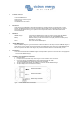
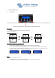
7 The VE.Net GMDSS Panel 7.1 Using the Panel Press cancel to leave a device, menu or value. Press ‘Enter’ to enter a device, menu or to change a value. Press the up and down switch to change a value or navigate through a menu. Reset the panel To reset the panel, press and hold “Cancel” for three seconds Navigating through the menu’s Device Setup Enter Cancel Device Menu Enter Cancel Device Readout Alarm Device Setup How to change a value with a VE.
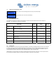
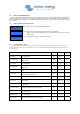
7.2 Where to find ”Panel Setup” menu GMDSS Monitor 24.7V 0.0A 100% Step 2.) Press “Enter” to enter the “Panel Setup” Panel Setup 7.3 Step 1.) Press “▼” to scroll through the menu until you see “Panel Setup”. The “Panel Setup” menu The properties of the panel are clarified in the table below. All values except the software version can be changed. In paragraph 7.1 it is explained how values can be adjusted.
.5 Alarms Whenever an alarm is active on the GMDSS charger, the VE.Net GMDSS panel will draw attention from the user while showing relevant information on the screen. The relay will also indicate the presences of an alarm. The relay is closed during normal operation. It is open for as long as one or more alarm conditions are present.
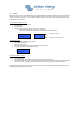
8.1 GMDSS Monitor Quick status line The GMDSS monitor is designed to give quick access to all relevant information, without having to scroll though abundant information. The ‘quick status’ simultaneous displays the most important parameters; the battery voltage, the battery current and the state-of-charge (SOC). In the root menu of the VE.Net GMDSS Panel you will see this screen GMDSS Monitor 24.7V -4.
8.3 Settings of the GMDSS Monitor In order to prevent accidental change of the settings of the GMDSS monitor, access to setup values during operation should in general be prevented. If the setup values are not visible, make sure the panel is in “User and Install” mode. For details about the access level, refer to paragraph 7.4. If the OEM installer has locked the panel at the user level, it is not possible to change the access level! 8.4 Where to find the “Setup Alarms” menu GMDSS Monitor 24.7V 0.
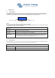
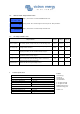
8.6 Where to find the “Setup Controller” menu GMDSS Monitor 24.7V 0.0A 100% Step 1.) Press “Enter” to enter the GMDSS Monitor menu. Step 2.) Press “▼” to scroll through the menu until you see “Setup Controller”. Consumed Ah 0.0 Setup Controller [Press Enter] 8.7 Step 3.) Press “Enter” to enter the Setup Controller menu. The “Setup Controller” menu Setup Controller Default Range Step size Battery Capacity The battery capacity in amp hours (Ah) at a 20h discharge rate.