
Manual


Pg. 20 Vicor 800-735-6200 Westcor Division 408-522-5280 Applications Engineering 800-927-9474 03-000049 rev A
PFC MicroS Design Guide
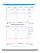
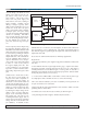
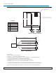
Figure 3. Cable Drawing
P1
24.0" +/- 1.0"
Power
T1
-V1
T2
-V2
Red, 22 AWG
Yellow, 22 AWG
Brown, 22 AWG
White, 22 AWG
Black, 22 AWG
12
34
56
1.74"
(44.2mm)
0.12"
(3.0mm)
1.500"
(38.1mm)
0.12"
(3.0mm)
0.900"
(22.9mm)
1.14"
(29.0mm)
0.13" (3.3mm) Dia Non
Plated thru hole 4
places
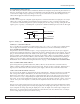
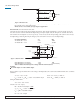
Molex CT43045F surface mountable
connector. .390" height above board.
Pin Description
1 Power
2T1
3 -V1
4T2
5 -V2
6
No Connection
J1 Pinout
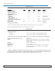
Figure 2. Mechanical Drawing
CURRENT SHARE BOARD -Continued
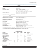
Specifications:
1. Power: 2-50Vdc at 5mA maximum.
2. Accuracy: +/- 1mV between -Vout connections.
3. Output current when not trimming up: +/- 1uA (VI-200/J00), +/-5uA (Maxi/Mini/Micro).
4. Use 4 non-plated through holes with standoffs for mounting.
5. CSB01 MUST be used for current sharing VI-200/VI-J00 converters.
6. CSB02 MUST be used for current sharing Maxi/Mini/Micro converters.
***PLEASE NOTE, THE CSB IS NOT INTENDED FOR HOTSWAP APPLICATIONS***
Contact your Regional Applications Engineer at 1-800-927-9474 for additional information.