PFC MicroS Design Guide PFC MicroS™ Power Factor Corrected AC-DC Switcher Design Guide and “Quick Install” Instructions www.vicorpower.
PFC MicroS Design Guide TABLE OF CONTENT Overview of Product...........................................................................................................................3 Part Numbering...................................................................................................................................4 Mechanical Considerations.................................................................................................................4 PFC MicroS Do’s and Don’ts.............
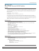
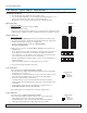
PFC MicroS Design Guide PFC MicroS™ Power Factor Corrected AC-DC Switcher Overview The PFC MicroS is an ultra low profile switching power supply that combines the advantages of power factor correction (PFC) with high power density. This guide covers both the standard and rugged COTS (MI) versions of the supply.
PFC MicroS Design Guide Part Numbering PFC MicroS PSx1-x2 x3(x4)-xxxx-x5 e.g. PS2-20-6544-G x1 Number of outputs x2 x3 Number of VI-200 & VI-J00 modules xxxx x5 Sequential number assigned by Westcor Optional Factory assigned Number of Maxi/Mini/Micro modules note: x5 = MI for rugged chassis, = MC for rugged chassis w/conformal coating Mechanical Considerations The PFC MicroS can be mounted on one of three surfaces using standard 8-32 or 4 mm screws. Maximum allowable torque is 5 in. lbs.
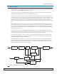
PFC MicroS Design Guide Technical Description The PFC MicroS consists of an off-line single phase, power-factor-corrected front end, EMI filter, cooling fan, customer interface, power supply control circuitry, associated housekeeping circuits, and a selection of Vicor’s VI-200/VI-J00 and/or Maxi/Mini/Micro DC-DC converters. Input AC mains voltage is applied to input connector MBJI. The input current is passed through an EMI filter designed to meet conducted noise limit "A" specifications of FCC Part 15.
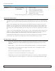
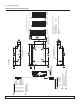
PFC MicroS Design Guide PFC MicroS “Quick Install” Instructions (For mechanical drawings, see page 8) Mounting the PFC MicroS * The PFC MicroS can be mounted on either of three sides. * Use #8-32 or 4mm mounting screws. Maximum penetration should not exceed 0.25 in. (6mm) on the side and 0.125 in. (3mm) on the bottom. * Maintain 2" (5,1cm) clearance at both ends of power supply for airflow. Input Connections Input Power MBJI * Input AC power is applied to connector MBJI. * Maximum torque is 5 in.lb.
PFC MicroS Design Guide Trim Connections for output connections with 16 pin Molex connectors: * S1J1-14 provides Trim access for output #1, and S1J1-6 provides Trim access for output #2, and S1J1-3 provides Trim access for output #3. * Use Molex mating receptacle #39-01-2160 with #39-00-0039 terminals. * Attach 18-24 AWG stranded wire using Molex tool #11-01-0197.
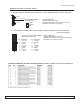
Pg. 8 Vicor 800-735-6200 2 1 SGND PGR ACOK N/C N/C N/C ED3 ED2 ED1 GSD PGDV Vcc Westcor Division 408-522-5280 AIR 1.29 32.69 FLOW A COMPLETE SET OF MATING CONNECTORS IS AVAILABLE BY SPECIFYING WESTCOR CONNECTOR KIT P/N: 19-130044 DIMENSIONS SHOWN ARE FROM BOTTOM SURFACE. MOUNTING PEMNUTS EXTEND.010 PAST BOTTOM SURFACE 2 3 1.29 32.
PFC MicroS Design Guide Output Connections for the PFC MicroS A. OUTPUT STUDS - SINGLE, DUAL OUTPUTS - when populated with full or half size module(s) -V OUT 10-32 OUTPUT STUDS SxJ2 REMOTE SENSE/TRIM PIN CONNECTOR +V OUT 3 2 1 MATING CONNECTOR: HOUSING: MOLEX (50-57-9403), TERMINAL FEM CRIMP 24-30 AWG: MOLEX (16-02-0103) USE CRIMP TOOL: MOLEX (11-01-0208) - SENSE + SENSE TRIM B.
PFC MicroS Design Guide Interface Connections Chassis Input Power Terminals (MBJI) Input AC power is applied through connector MBJI using Molex mating connector 39-01-4051. Use 16 AWG wire with Molex Socket Pin 39-00-0090 and Crimp Tool 11-01-0199. A fault clearing device, such as a fuse or circuit breaker, with a maximum 10A rating at the power supply input is required for safety agency compliance. It should be sized to handle the start-up inrush current of 8.5A peak at 115 Vac and 17A peak at 230 Vac.
PFC MicroS Design Guide User Interface Connections Signal Ground (CBJ3-1) Signal Ground on CBJ3-1 is an isolated secondary ground reference for all CBJ3 interfacing signals. This is not the same as Earth Ground on input power connector MBJI. Bi -directional I/O lines (CBJ3-7 to CBJ3-9) (Enable/Disable or Module Power Good Status) Enable/Disable Mode Enable/Disable mode is the default condition for these I/O lines. In this mode, the control pins allow the outputs to be sequenced either ON or OFF.
PFC MicroS Design Guide PowerGood Read with Good Module PowerGood Read with Defective Module Pg.
PFC MicroS Design Guide General Shutdown /GSD (CBJ3-10) The GSD control pin on CBJ3-10 allows simultaneous shutdown of all outputs. This pin must be pulled down to less than 0.7V, and will typically source 250μA (1mA maximum) to shut down all outputs. The GSD pin should be open circuited or driven high to a logic high voltage of 3.5V or greater when not in use, or when the outputs are to be enabled. Do not apply more than 5V to this input at any time.
PFC MicroS Design Guide +Out +Sense Use 20-22 AWG Twisted Pair Wires Load -Sense -Out Figure 5. Remote Sense The Sense connector for a single and dual output board is a 3 pin connector providing the +Sense connection on Pin 2 and the -Sense connection on Pin 3.
PFC MicroS Design Guide Specifications (Typical at 25°C, nominal line and 75% load, unless otherwise specified) GENERAL 1-3 VI-200/VI-J00: One VI-200 or Two VI-J00s Maxi/Mini/Micro: One Maxi, Two Minis or Three Micros Typically > 75% cURus – UL 60950-1, CSA 60950-1; cTUVus – EN 60950-1, UL 60950-1, CSA 60950-1 CE Mark – Low Voltage Directive, 2006/95/EC note: certain wide temp range units will not carry all approvals 500W at 115 Vac (100 Vac minimum input) + Number of Outputs Modules Efficiency Safety Age
PFC MicroS Design Guide OUTPUT (CONT’D.) Maxi/Mini/Micro Modules Parameter Setpoint Accuracy* Load/line Regulation Temperature Regulation Long Term Drift Output Ripple and noise: ≤ 10V out > 10 V out Voltage Trim Range Maxi/Mini/Micro Slots Total Remote Sense Compensation OVP Set Point Current Limit Overtemperature Limiting MIN. TYP. MAX. UNITS ±0.5 ±1 % of VNOM ±0.08 ±0.45 ( ±7) % of VNOM 0% to 100% 0.002 0.02 0.005 %/°C %/K hours -20 to 100°C 100 1.
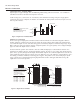
PFC MicroS Design Guide Output Power Derating PFC MicroS Output Power vs. DC Input Voltage 600 Ouutput Power (Watts) 550 Power Limit Exceeded 500 Safe Operating Area 450 400 350 100 120 140 160 180 200 220 240 260 280 300 Input Voltage (DC) 03-000049 rev A Vicor 800-735-6200 Westcor Division 408-522-5280 Applications Engineering 800-927-9474 Pg.
PFC MicroS Design Guide Output Power Derating - Continued 1. For all module configurations. The PFC MicroS or an individual output may be limited by module power limitations e.g. 5V Maxi module is 400W maximum. One cannot exceed the output power rating of the PFC MicroS regardless of the module capability. 2. Also see Output Power vs Input Voltage charts on page 16. Pg.
PFC MicroS Design Guide CURRENT SHARE BOARD - Optional Feature "Current sharing" also known as Load Sharing, is the ability to divide the output current evenly across all active power supplies. This greatly reduces stresses on each power supply and allows them to run cooler, resulting in higher reliability. Standard "current sharing" techniques typically utilize shunt resistors or Hall Effect devices to measure the current from each power supply.
PFC MicroS Design Guide CURRENT SHARE BOARD -Continued 0.13" (3.3mm) Dia Non Plated thru hole 4 places 1.74" (44.2mm) 2 1 4 3 6 5 Molex CT43045F surface mountable connector. .390" height above board. 1.500" (38.1mm) J1 Pinout Pin 1 2 3 4 5 6 Description P ow e r T1 -V1 T2 -V2 No Connection 0.12" (3.0mm) 0.12" (3.0mm) 0.900" (22.9mm) 1.14" (29.0mm) Figure 2. Mechanical Drawing 24.0" +/- 1.
PFC MicroS Design Guide Notes 03-000049 rev A Vicor 800-735-6200 Westcor Division 408-522-5280 Applications Engineering 800-927-9474 Pg.
PFC MicroS Design Guide VICOR GLOBAL OFFICES USA EUROPE Vicor Corporation, Corporate Headquarters 25 Frontage Road Andover, MA 01810 Tel: 800-735-6200, Tel: 978-470-2900 Fax: 978-475-6715 Vicor France Tel: 33-1-3452-1830 Free Phone France Only: 0800 419 419 Fax: 33-1-3452-2830 Email: vicorfr@vicr.com Vicor Germany Tel: +49-89-962439-0 Free Phone Germany Only: 0800 018 29 18 Fax: +49-89-962439-39 Email: vicorde@vicr.com Vicor Corporation 377 E.