
User guide

PFC Micro Design Guide
Example:
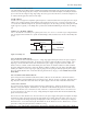
±10% trim adjust on a 12V nominal output.
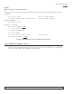
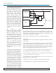
Figure 6 shows a typical variable trim circuit. Using a 10k trimpot (R7), the resistor values for R6 and R8 can be calculat-
ed as follows:
V
1
= V
ref
+ 10% = 2.75V Given: V
ref
= 2.5V (see Table 2)
I
R5
= (2.75V - V
ref
)/R
TH
= (2.75V - 2.5V)/10kΩ = 25μA Given: R
TH
= 10kΩ (see Table 2)
Setting the bottom limit:
V
R6
= 2.5V - 10% = 2.25V
And since I
R5
= I
R6
= 25μA,
R6 = V
R6
/I
R6
= 2.25V/25μA = 90kΩ
V
2
= V
1
+ V
R6
= 2.75V + 2.25V = 5V
I
R7
= V
2
/R7 = 5V/10kΩ = 500μA
I
R8
= I
R7
+ I
R6
= 525μA
V
R8
= (V
nom
+10%) - V
2
= 13.2V - 5V = 8.2V Given: V
nom
= 12V
R8 = V
R8
/I
R8
= 8.2V/525μA = 15.62kΩ
Consult Applications Engineering when trimming outputs below 5V.
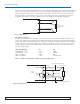
Single Output Power Supplies (Arrays)
Westcor’s standard configuration for single output power supplies is to set the left module (as seen from looking
at the power supply output) as the controlling module of the array.
03-000048 rev A Vicor 800-735-6200 Westcor Division 408-522-5280 Applications Engineering 800-927-9474 Pg. 15