
Install Instructions


VT8000 Series
17
ZigBee Pairing Procedure
Viconics Technologies Inc. | 9245 Langelier Blvd. | St.-Leonard | Quebec | Canada | H1P 3K9 | Tel: (514) 321-5660 | Fa x : (514 ) 321-4150
028-0450-00
www.viconics.com | sales@viconics.com November 2014
© 2014 Viconics TEchnologies. All rights reserved.
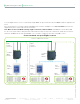
To use the ZigBee wireless sensors in a network with multiple MPMs, the general network architecture must resemble the diagram shown
below.
If the general design of your network installation with MPMs, Room Controllers and ZigBee sensors does not match that shown in the
diagram below, please contact Support for more information.
Note: Make sure that each MPM controlling a ZigBee network has a different PAN ID. If the MPMs do not have different PAN
IDs, the sensors will be unable to distinguish which network with which they are supposed to communicate, and this will cause them to
malfunction. All MPMs have the same default PAN ID, so it is essential to configure the value when using ZigBee sensors.
IP/UDP or CANbus wired connection
ZigBee
network 1
Channel: 15
Room
Controller
PAN ID: 3
ZigBee
end devices
ZigBee
network 2
Channel: 25
Room
Controller
PAN ID: 4
ZigBee
end devices
Room
Controller
PAN ID: 5
ZigBee
end devices
Correct network set up for ZigBee sensors
Coordinator
(MPM)
PAN ID: 1
Coordinator
(MPM)
PAN ID: 2