
User Manual


4
Getting Started
6. ClickApply, then OK.
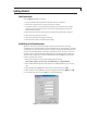
7. Onthenextscreen,selectFile > Properties >
Settings, and click on ASCII Setup.
8. IntheASCIIsetupwindow,clickthecheck
boxes or enter the values as required to
match the screen in Figure 3.
9. Click OK, then OK again to close the FTC
Properties window.
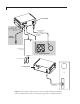
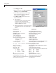
10. HyperTerminal:
Click on the phone icon just below “View”
to connect. If the connection is not
available, repeat the procedure, selecting
adifferentCOMportinstep4.
11. WhenHyperTerminalisconnected,pressthe
reset button of the FTC. The FTC will read as
follows:
FTC Response Explanation
Resetting PWM . . . ok Pulse Width Modulator working
A/D started Analog to Digital converter working
EEPROM parameters recovered Operational parameters loaded
DS24B33present Memory chip recognized
1-wirechecksumok Verify chip is OK
ID=00000142F5DA Chip ID number
Reading embedded parameters … Reading column data
Columnid:12345 Column serial number
Lengthm:10 Column length in meters
Phaseid:VB-1250um Column phase, film thickness (µm) & inside diameter (µm)
Element equation : Column temperature vs. resistance equation
R(T) = 1.31039E1 + 6.44364E-2 * T + 1.74357E – 4 * T^2
M=1.550 Heat capacity of the column
Alpha=2.10000E-2 Time constant in seconds, how fast does the temp. rise
Lambda=1.00000E-4 PWM dampener
Max.temp=340 Column maximum temperature
Calibration data : Column resistance and temperature calibration data
140.0005.600 pair #1 (*C) (ohms)
2183.00010.692 pair #2 (*C) (ohms)
3300.00017.785 pair #3 (*C) (ohms)
OK Data accepted
Weighting vector generated. Algorithm calculation complete
Checking input connections . . . ok If not “ok”, check column connections
0.4.8.095July5201212:30:55,Unit#321 FTC firmware and serial number
DSP Column Control online FTC ready for use
Figure 4: ASCII setup