Valco Instruments Co. Inc. Fast Temperature Programmer Operator’s Manual FTP Rev 11/13 North America, South America, and Australia/Oceania contact: ® Valco Instruments Co. Inc. 800 · 367· 8424 713 · 688· 9345 713 · 688· 8106 valco@vici.com sales tech fax Europe, Asia, and Africa contact:: ® VICI AG International Schenkon, Switzerland Int + 41 · 41 · 925· 6200 Int + 41 · 41 · 925· 6201 info@vici.
This page intentionally left blank for printing purposes
Table of Contents Introduction.................................................................................................................................................. 1 General Description.......................................................................................................................... 1 Parts Included...................................................................................................................................... 1 Getting Started.......................
This page intentionally left blank for printing purposes
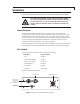
1 Introduction Please read the manual completely before using the Fast Temperature Controller. The column controlled by the FTC will be heated very rapidly to a very high temperature (450°C). Do not touch the column at any time the FTC is on. Do not handle the column unless the FTC has been turned off for at least 15 minutes, and then use caution.
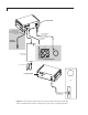
2 Figure 2: Connecting the components to the rear panel (top) and front panel (bottom) of the Fast Temperature Controller. Components in gray boxes are supplied separately.
3 Getting Started Cable Connections Refer to Figures 1 and 2 as necessary. 1. Connect the USB cable to the front of the FTC and to the computer. 2. Connect the column harness to the FTC and to the column. 3. A 12 VDC fan with a 1.0 amp maximum average may be used to cool the column, under the control of the FTC. Connect the red wire of the fan harness to the red (positive) wire on the fan. 4. Connect the black wire of the fan harness to the black (negative) wire of the fan. 5.
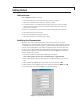
Getting Started 4 6. Click Apply, then OK. 7. On the next screen, select File > Properties > Settings, and click on ASCII Setup. 8. In the ASCII setup window, click the check boxes or enter the values as required to match the screen in Figure 3. 9. Click OK, then OK again to close the FTC Properties window. 10. HyperTerminal: Click on the phone icon just below “View” to connect. If the connection is not available, repeat the procedure, selecting a different COM port in step 4. 11.
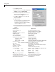
Getting Started 5 Viewing the Command Set To view the list of commands for the FTC, type ??. All HyperTerminal commands must be followed by on the keyboard. Characters may be in either upper or lower case. You may wish to print the list for for reference.
Getting Started 6 Verifying Column Parameters Remember that commands can be upper or lower case, and that they must always be followed by . To verify that the column parameters have been correctly loaded into the FTC, type SC (for “show column”). The column parameters should match those on the data sheet supplied with the column. : sc Column id/sn: 12345 Column serial number Max. temperature: 325 Maximum column temperature in °C Calibration data: Temp. Res. 40.00 6.30000 183.00 11.
7 Programming and Running a Sequence Entering Data for the States Heating and cooling sequences are controlled by states. State 1 is the idle-mode (starting) temperature, with no ramp. States 2 to 8 are programmable by ramp rate, end temperature, and hold time, for as long as the state is active. States are observed in order, while any state indicated as inactive is skipped. States may be turned on and off by electing the states active (Yes) or inactive (No).
Programming and Running a Sequence 8 3. Type SS2 and type the values below for example state 2, followed by . : ss2 Active (Y)? (no change) Ramp rate, degC/min (0):100 Setpoint (0):100 Hold time, seconds (0):10 3. Type SS3 and type the values below for example state 3, followed by . : ss3 Active (N)? Y Ramp rate, degC/min (0):200 Setpoint (0):200 Hold time, seconds (0):30 4. Type SS4 and type the values below for example state 4, followed by .
Programming and Running a Sequence 9 Logging Column Data Data logging allows the user to view column information collected by the FTC. Turn on data logging, type L+. To stop logging data, type L-. The data is presented as follows: Total Time (sec) Target Temp Measured Temp Tt-Tm Voltage Current PWM State Flag 00000001.0 40.00 40.000 0.000 0.6110 0.1038 983 1R 00000002.0 40.00 40.000 0.000 0.6110 0.1038 983 1R 00000003.0 40.00 40.000 0.000 0.6110 0.
Programming and Running a Sequence 10 Starting the Sequence Before the column ramp sequence will start, the column must be turned on and there must be a “ready” flag viewable in the data log, indicating that the equilibration time has elapsed. As soon as the “ready” signal is received, the ramp sequence may be restarted by typing GO. Once the heating cycle is complete, the fan will be turned on to cool the column to the stage 1 starting temperature.
11 Fan Installation and Modes Installation 1. Before turning on the fan, verify that the power to the column is off (Z-), to prevent column damage. 2. To test the connections, turn on the fan by typing F+. If it does not come on, check the connections and/or replace the fan. 3. Turn off the fan by typing F-. Mode Descriptions The cooling fan has four modes: 0 Off 1 The fan is always on. (This will generally never be used.
Fan Installation and Modes 12 To View or Change the Fan Mode To view the current fan mode setting: 1. Type FM. The response will be : fm 2 (or 0, 1, or 3) 2 indicates that the fan is in the default mode 2. To change the fan mode setting to 0, for example: 1. Type FM=0 2. Verify that the change was made by typing FM. The response should be : fm 0 To View or Change the Drop Out Temperature The drop out temperature applies only in mode 2.
13 Optional Electronic Control External electronic control of the FTC is provided by a 5 volt, low-true, (1 ma drive) logic level interface. An external input/output (I/O) cable is used for this purpose. To start the programmed heating sequence remotely, momentarily connect the orange and black wires. Additional signals, listed in the table below, are available for custom applications. Please contact Valco for further assistance.
14 Warranty This Limited Warranty gives the Buyer specific legal rights, and a Buyer may also have other rights that vary from state to state. For a period of 365 calendar days from the date of shipment, Valco Instruments Company, Inc. (hereinafter Seller) warrants the goods to be free from defect in material and workmanship to the original purchaser.