Valco Instruments Co. Inc. Pulsed Discharge Detector Model D-4-I-SH17-R Instruction Manual D4_shim_17.P65 Rev. 5/12 North America, South America, and Australia/Oceania contact: Valco Instruments Co. Inc. 800 · 367· 8424 713 · 688· 9345 713 · 688· 8106 valco@vici.com sales tech fax Europe, Asia, and Africa contact:: VICI AG International Schenkon, Switzerland Int + 41 · 41 · 925· 6200 Int + 41 · 41 · 925· 6201 info@vici.
This page intentionally left blank for printing purposes
Table of Contents Introduction Description and Operating Principles ..............................................................1 Safety Notes and Information..........................................................................2 Symbols Installation Category Safety Components of the Detector System ..............................................................3 System Requirements Components not Included with the Detector System ......................................4 System Purity ..................
This page intentionally left blank for printing purposes
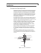
1 Introduction Description and Operating Principle The PD-D-4-I-SH17-R is a non-radioactive pulsed discharge ionization detector (PDID) which is optimized for the Shimadzu GC -17, GC-2010, and GC-2014. A schematic representation of the basic D4 detector is shown in Figure 1. The D4 utilizes a stable, low power, pulsed DC discharge in helium as the ionization source.
Introduction 2 Helium Ionization (PDHID) The PDHID is essentially non-destructive (0.01 - 0.1% ionization) and highly sensitive. The response to organic compounds is linear over five orders of magnitude with minimum detectable quantities (MDQs) in the low or sub picogram range. The response to fixed gases is positive (the standing current increases), with MDQs in the low ppb range. The PDHID response is universal except for neon, which has an ionization potential of 21.56 eV.
Introduction 3 Components of the Detector System Detector system components are listed in Table 1. Check the contents of the packages to verify that everything is present. Contact the factory if anything is missing or damaged. (NOTE: damaged shipments must remain with the original packaging for freight company inspection.) Table 2 lists additional items which must be purchased from Shimadzu.
Introduction 4 System Requirements Components Not Included with the Detector System • Helium (99.
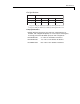
Introduction 5 Gas Specifications Detector Mode PDHID Ar-PDPID Discharge gas Helium 2% Ar in He Carrier gas Helium * Kr-PDPID Xe-PDPID 1.5% Kr in He 0.8% Xe in He ** ** ** Any gas including He which has an ionization potential greater than 12 eV ** Any gas including He which has an ionization potential greater than 11 eV Purity Specifications • Helium (discharge and carrier gas) must have a minimum purity of 99.999%, with < 20 ppm Ne impurity.
6 Installation General Precautions • Do not use plastic/polymer or copper tubes for gas handling and interconnectons. Use only stainless steel tubing with Valco gold-plated ferrules. • Do not turn the unit on until the helium discharge gas is flowing through the detector. • Do not shut off or disconnect the discharge gas when the detector is hot, even if the unit is turned off. Turn off the discharge and allow the detector to cool down naturally before disconnecting or shutting off the discharge gas.
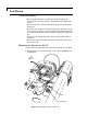
7 TO PULSER MODULE FROM UPPER DETECTOR ELECTODE FROM LOWER DETECTOR ELECTODE Figure 4: Mounting the detector on a GC-2010 or GC-2014
Installation 8 Gas Connections Remember these three points discussed earlier: (1) all surfaces that contact the gas stream must be fused silica or stainless steel; (2) do not use copper tubing or brass fittings; and (3) all tubes must be thoroughly cleaned and baked before use. The installation instructions below assume that the detector discharge gas will be supplied from a nearby cylinder of helium of the proper purity.
Installation 9 7. Open the cylinder valve to pressurize the regulator once again. Close the valve and observe the needle of the high pressure gauge for 15 minutes. If it doesn’t move, there is no critical leak on the high pressure side of the regulator. CAUTION: Never use leak detecting fluids on any part of this system. Installing and Purging the Helium Purifier EZR21 1.
Installation 10 Capillary Column Connection If the capillary column adapter is installed in the column inlet: COLUMN INLET CAPILLARY COLUMN ADAPTER (IZERA1.5) COLUMN FERRULE 11.4 cm/ NUT CAPILLARY COLUMN 1. Make a mark on the column 11.4 cm from the end. 2. Remove the knurled nut and plug from the capillary column adapter in the column inlet at the bottom of the detector. Slide the nut over the end of the column, followed by the appropriate column ferrule (FS.4 or FS.5, or ZF.5V for megabore). 3.
Installation 11 3. Set aside the 1/8" wrench and completely remove the adapter from the column inlet. 4. Screw the packed column adapter into the column inlet by hand. Exercise caution, as the tip of the adapter is very fragile. Then tighten the adapter with a 1/4" wrench, using an additional wrench on the flats of the column inlet to support the detector. 5. Connect the 1/8" column to the packed column adapter with the EZRU21 reducing union supplied in the fittings kit.
Installation 12 Pulser Module Installation 1. GC-17: The pulser module can usually be mounted on the bottom plate of the GC, using existing holes. (Figure 6) If there is no room on the bottom plate, mount the module on the top of the GC oven. GC-2014: There is room for the pulser module in a compartment on the right side (facing the instrument), at the back near the top. (Figure 7) GC-2010: The best place is a space in the rear on the left hand side. (facing the instrument).
Installation 13 POSSIBLE LOCATION FOR PULSER MODULE ON GC-2014 Figure 7: Possible location for the pulser module on the GC-2014 Figure 8: Possible location for the pulser module on the GC-2010
Installation 14 Detector Electrical Connections CAUTION: Do not use a wrench to tighten the SMC connectors on the bias and electrometer cables. Connections should be finger tight only. 1. Referring to Figure 9 as necessary, connect the BIAS cable to the top electrode and the electrometer cable (ELECT) to the bottom electrode.
Installation 15 Initial Power-Up CAUTION: Always make sure that discharge gas is flowing before heating and powering up the detector. 1. Before installing the column, set the gas flow to 30 ml/min (measured at the detector vent). Let it flow for 15 minutes so that all air is purged from the helium purifier. 2. Plug in the helium purifier and turn on the GC. 3. Set the detector temperature to 100°C and allow time for the detector and helium purifier to reach the set temperature. 4.
16 Mode Selection and Setup Helium Ionization Mode If the instructions of Step 1 at the top of page 10 were properly executed, the column should already be properly positioned. Since there may be some variation in the flow rate for the different types of capillary columns, the user may want to optimize the column position within this suggested range. DO NOT insert the column more than 11.6 cm.
17 Ar-PDPID Changing the discharge gas from helium to a mixture of 2% argon in helium changes the photon energy level from the 17 - 13.5 eV range to the 11.8 - 9.8 eV range. The argon emission consists of resonance radiation at 11.8 eV and 11.6 eV and the diatomic Ar2 emission in the range of 9.2 - 10.3 eV. Except for fixed gases and a few organic compounds like CH4 (IP = 12.5 eV), CH3CN (IP = 12.
18 Troubleshooting High Background Current The detector isn’t leaking. Check for column bleed and/or leaks in the GC setup. Baseline current falls to normal range (< 20.0 mV) Disconnect the column and cap the column inlet Baseline current is still high (> 20.0 mV) Consult Valco Baseline current is still high (> 20.0 mV) Pink Check discharge color Baseline current falls to normal range (< 20.0 mV) Baseline current falls to normal range (< 20.
19 High Noise Level If the noise lievel is high: 1. See if it improves with the GC fan turned off. 2. Check the column insertion position (11.4 cm for capillary columns, 9.8 cm for packed columns.) 3. If the noise level is still high, do a hydrogen leak test, described below. 4. If there are no leaks found, or leaks are found and repaired and the noise level is still high, consult Valco.
20 Warranty This Limited Warranty gives the Buyer specific legal rights, and a Buyer may also have other rights that vary from state to state. For a period of 365 calendar days from the date of shipment, Valco Instruments Company, Inc. (hereinafter Seller) warrants the goods to be free from defect in material and workmanship to the original purchaser.
21 Detector Performance Log In addition to the occasions indicated in the Comments area of the table below (see Initial Power-Up, page 15), the standing current should be observed and logged after any system change. Logging the standing current (with and without the column) on a regular basis is also an effective monitor of system integrity (leaktightness and cleanliness). To check sensitivity continuity, we recommend tracking the internal standard (quantity on column/area count).