
Instruction Manual


5
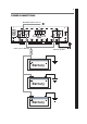
TERMINALS AND CONNECTIONS
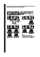
3. Speaker Output Terminal
For connection to the speakers. See page 8 and 9 for wiring examples.
4. Low Level Input
For connection to any sour ce (head unit) with a low level output. This is your RCA output fr om the
source (headunit)
5. Low Level Output
Used to connect additional amplifiers with RCA input.
6. Power / Protect LED
W hen the amplifier is operating cor rectly the gr een LED will illuminate.
W hen the amplifier is in protection mode t he r ed LED will illuminate.
7. Gain Control
Used to match t he input signal of the sour ce to t he amplifier. See the setup section for m or e details.
8. Subsonic Filter Control
This contr ol allows the subsonic filter fr equency to be set , the filter is adjustable from 1 0 Hz to 7 0 Hz.
9. Bass Boost level Control
This contr ol pr ovides up to an extra +9 dB of bass boost at the chosen frequency. Use t his boost to
increase bass output fr om the amplifier.
10. Bass Boost Frequency Control
This contr ol sets the frequency that will be boosted by the bass boost control, t he frequency ranges
fr om 3 0 Hz to 9 0 Hz.
11. Low Pass Crossover Control
This contr ol is used to set the cr ossover point for t he amplifier .
The frequency ranges on the low pass filter are from 3 5 Hz to 2 5 0 Hz.
12. Phase Control
This allows t he phase of the amplifier to be adjusted from 0 to 1 8 0 degr ees.
2. Power Input 1
Only 0 gauge cable should be used for the power and ground connection t o the am plifier .
The power cable should connect dir ectly t o the batter ies with a 9 0 0 amp fuse inline no
fur ther t han 1 8 inches in wire length fr om the battery and this fuse must be fitted befor e
the power cable enter s a bulkhead.
Please ensur e that the fuse is not fitted until inst allation is complete and all wiring is checked.
Rubber gr om mets must be used when passing the power cable thr ough a bulkhead to
pr event the cable becoming chaffed or cut.
The ground cable should be connected directly to the chassis ground of the vehicle and ideally
to bare met al.
The ground cable length should be kept to an absolute m inimum.
It is not r ecommended that you connect the ground cable to the vehicles seat belt ancor points.
A minimum of 1 8 gauge cable should be used for t he r emot e tur n on connection.
The cable should be run with the sam e car e and attention as the power cable and use gromm ets
if necessar y.