
User`s manual


BIOS Setup
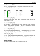
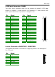
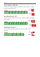
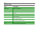
LVDS Panel Connector: PANEL
The LVDS Panel connector allow you to connect the panel’s LVDS cable
directly to support 2 single-channel LVDS panels or 1 dual-channel LVDS
panel (optional) without any need of a daughter card.
Pin Signal Pin Signal
1 PVDD2 2 PVDD1
3 PVDD2 4 PVDD1
5 PVDD2 6 PVDD1
7 GND 8 GND
9 -LD2C4 10 -LD1C0
11 +LD2C4 12 +LD1C0
13 GND 14 GND
15 -LD2C5 16 -LD1C1
17 +LD2C5 18 +LD1C1
19 GND 20 GND
21 -LD2C6 22 -LD1C2
23 +LD2C6 24 +LD1C2
25 GND 26 GND
27 -LCLK2 28 -LCLK1
29 +LCLK2 30 +LCLK1
31 GND 32 GND
33 -LD2C7 34 -LD1C3
35 +LD2C7 36 +LD1C3
37 SPCLK1 38 GPIOA_CLK
39 SPD1 40 GPIOB_DATA
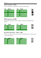
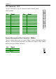
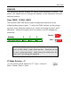
Inverter Connectors: INVERTER1 / INVERTER2
The mainboard provides 2 inverters for supplying power to the backlight of
the LCD panel.
Pin Signal
1 IVDD
2 IVDD
3 BLON
4 NC
5 BLON
6 BR_CNTR
7 GND
8 GND
2
1
40
39
1