User’s Manual EPIA-EX Version 1.
Copyright Copyright © 2006 VIA Technologies Incorporated. All rights reserved. No part of this document may be reproduced, transmitted, transcribed, stored in a retrieval system, or translated into any language, in any form or by any means, electronic, mechanical, magnetic, optical, chemical, manual or otherwise without the prior written permission of VIA Technologies, Incorporated. Trademarks All trademarks are the property of their respective holders. PS/2 is a registered trademark of IBM Corporation.
FCC-B Radio Frequency Interference Statement This equipment has been tested and found to comply with the limits for a class B digital device, pursuant to part 15 of the FCC rules. These limits are designed to provide reasonable protection against harmful interference when the equipment is operated in a commercial environment.
Safety Instructions 1. Always read the safety instructions carefully. 2. Keep this User's Manual for future reference. 3. Keep this equipment away from humidity. 4. Lay this equipment on a reliable flat surface before setting it up. 5. The openings on the enclosure are for air convection hence protects the equipment from 6. Make sure the voltage of the power source and adjust properly 110/220V before overheating. DO NOT COVER THE OPENINGS. connecting the equipment to the power inlet. 7.
B OX C ONTENTS One One One One One VIA Mini-ITX mainboard Quick Installation Guide ATA-133/100 IDE ribbon cable driver and utilities CD IO bracket i
T ABLE OF C ONTENTS Box Contents ......................................................................... i Table of Contents ..................................................................ii Chapter 1 ............................................................................ 1 Specifications .................................................................... 1 Mainboard Specifications ..................................................... 2 Mainboard Layout.........................................
CPU & PCI Bus Control ....................................................... 45 TV Output Connector ......................................................... 46 Integrated Peripherals ....................................................... 47 VIA OnChip PCI Device....................................................... 48 USB Device Setting ............................................................ 49 Power Management Setup .................................................. 51 Wakeup Event Detect.........
This page is left intentionally blank.
CHAPTER 1 Specifications The ultra-compact and highly integrated VIA EPIA-EX uses the Mini-ITX mainboard form-factor developed by VIA Technologies, Inc. as part of the company’s open industry-wide total connectivity initiative. The mainboard enables the creation of an exciting new generation of small, ergonomic, innovative and affordable embedded systems. Through a high level of integration, the Mini-ITX occupy 66% of the size of FlexATX mainboard form factor.
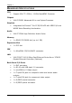
Chapter 1 M AINBOARD S PECIFICATIONS CPU • Support VIA C7 1.5GHz / 1.
Specifications Onboard I/O Connectors • 1 x USB pin connector for 4 additional USB 2.
Chapter 1 M AINBOARD L AYOUT 4
Specifications B ACK P ANEL L AYOUT 5
Chapter 1 B ACK P ANEL P ORTS Port Description S/PDIF DVI S-Video RJ45 USB RCA Jacks S/PDIF Ports DVI Port S-Video port RJ45 port USB 2.
Specifications O NBOARD C ONNECTORS Connector Description ATXPWR CPUFAN SYSFAN +12V IDE F_PANEL F_AUDIO KBMS LPC LVDS SATA 1-2 SMBus USB_1/2 CD_IN 1394_1 VIP SCART and D-terminal Power cable connector CPU fan connector System fan connector +12V power connector IDE drive connector Front panel connector Front Audio connector Keyboard and Mouse connector LPC connector LVDS connector Serial ATA 1 and 2 connectors SMBus connector Universal Serial Bus 2.
CHAPTER 2 Installation This chapter provides you with information about hardware installation procedures. It is recommended to use a grounded wrist strap before handling computer components. Electrostatic discharge (ESD) can damage some components.
Installation CPU The VIA EPIA-EX Mini-ITX mainboard can support VIA C7 NanoBGA2 Processors. The processor requires a heatsink with fan for 1.5GHz SKU and a fanless heatsink for 1.0GHz SKU.
Chapter 2 CPU Fan and System Fan: CPUFAN and SYSFAN The CPUFAN (CPU fan) and SYSFAN (system fan) run on +12V and maintain system cooling. When connecting the wire to the connectors, always be aware that the red wire is the Positive and should be connected to the +12V. The black wire is Ground and should always be connected to GND.
Installation MEMORY MODULE INSTALLATION The VIA EPIA-EX Mini-ITX mainboard provides one 240-pin DIMM slot for DDR2 533 SDRAM memory modules and supports the memory size up to 1GB. DIMM DDR2 SDRAM Module Installation Procedures • Locate the DIMM slot in the motherboard. • Unlock a DIMM slot by pressing the retaining clips outward. • Align a DIMM on the socket such that the notch on the DIMM matches the break on the slot.
Chapter 2 CONNECTING THE POWER SUPPLY The VIA EPIA-EX Mini-ITX mainboard supports a conventional ATX power supply for the power system. Before inserting the power supply connector, always make sure that all components are installed correctly to ensure that no damage will be caused. ATX 20-Pin Power Connector To connect the ATX power supply, make sure the power plug is inserted in the proper orientation and the pins are aligned. Then push down the plug firmly into the connector.
Installation BACK PANEL PORTS The back panel has the following ports: S/PDIF Ports This mainboard enables digital audio output through either the coaxial or optical SPDIF port. DVI Port The DVI-I connector allows you to connect to DVI display. S_Video Port The black port allows you to connect TV monitor or S-video device to the mainboard.
Chapter 2 RJ45 10/100 LAN and USB Ports The mainboard provides a standard RJ-45 and two USB 2.0 ports. These ports allow connection to a Local Area Network (LAN) through a network hub and USB 2.0 devices. RCA Jack The top three RCA jacks enable you to connect to displays using component video signals. The bottom three RCA jacks enable you to connect to displays using the yellow composite video jack. The red and white RCA jacks are for audio output.
Installation CONNECTORS Hard Disk Connectors: IDE The mainboard has an Ultra DMA 133/100/66/33 controller. You can connect up to two hard disk drives, CD-ROM and other devices. IDE 1 If two drives are connected to a single cable, the jumper on the second drive must be set to slave mode. Refer to the drive documentation supplied by the vendor for the jumper settings.
Chapter 2 Case Connector: F_PANEL The F_PANEL pin header allows you to connect the power switch, reset switch, power LED, sleep LED, HDD LED and the case speaker. Pin Signal Pin Signal 1 3 5 7 9 11 13 15 +5V +5V -PLED_2 +5V NC NC SPEAK Key 2 4 6 8 10 12 14 16 +5V HD_LED PW_BN GND RST_SW GND +5V -SLEEP_LED F_PANEL 1 2 15 16 Power Switch (PW_BN) Connect to a 2-pin power button switch. Pressing this button will turn the system power on or off.
Installation Front Panel Audio Connector: F_AUDIO This is an interface for the VIA front panel audio cable that allow convenient connection and control of audio devices. By default, the pins labeled AUD_FPOUT_R / AUD_RET_R and the pins AUD_FPOUT_L / AUD_RET_L are shorted with jumper caps. Remove the caps only when you are connecting the front panel audio cable.
Chapter 2 LPC Connector: LPC This pin connector is for LPC devices. LPC 1 Pin Signal Pin Signal 1 3 5 7 9 11 13 15 17 19 LAD1 -PCIRSTX LAD0 LAD2 SERIRQ -LDRQ1 +5V +5V GND GND 2 4 6 8 10 12 14 16 18 20 LPCCLK1 GND SIO_OSC -LFRAME LAD3 -EXTSMI +3.3V +3.3V GND Key 19 2 20 LVDS Connector The LVDS connector allows you to connect the panel’s LVDS cable directly to support LVDS panel without any need of a daughter card.
Installation Serial ATA Connectors: SATA1 and SATA2 SATA1-2 These next generation connectors support the thin Serial ATA cables for primary internal storage devices. The current Serial ATA interface allows up to 150MB/s data transfer rate, faster than the standard parallel ATA with 133 MB/s (Ultra DMA). System Management Bus Connector: SMBUS This pin header allows you to connect SMBUS (System Management Bus) devices.
Chapter 2 CD Audio Connector: CD_In This pin header allows you to receive stereo audio input from sound source such as a CD-ROM. Pin Signal 1 2 3 4 LINEIN_L GND GND LINEIN_R 1 CD_IN FireWire Connector: 1394_1 FireWire is a serial I/O interface that provides you fast data transfer rates. The mainboard has one FireWire pin header to provide PC connectivity for a wide range of devices, including consumer electronics audio/video (A/V) appliances, storage peripherals, other PCs and portable devices.
Installation SCART & D-Terminal (Optional) Mainboards fitted with the optional SCART / D-Terminal connector enables users to connect a SCART / D-Terminal port for connecting to audio/visual equipment. Pin Signal Pin Signal 1 3 5 7 9 11 13 15 17 19 AUDIO_R AUDIO_L +2.
Chapter 2 JUMPERS The mainboard provides jumpers for setting some mainboard functions. This section will explain how to change the settings of the mainboard functions using the jumpers. Clear CMOS: CLEAR_CMOS The onboard CMOS RAM stores system configuration data and has an onboard battery power supply. To reset the CMOS settings, set the jumper on pins 2 and 3 while the system is off. Return the jumper to pins 1 and 2 afterwards. Setting the jumper while the system is on will damage the mainboard.
Installation Panel Power Selector: PVDD_SEL PVDD_SEL PVDD_SEL PVDD_SEL PVDD is the VCC selector jumper to 1 3 1 3 1 3 determine the panel’s signal voltage. 2 4 6 5 2 4 6 5 4 6 5 +5V +12V 2 +3.3V Setting 1 2 3 4 5 6 +12V +5V +3.
Chapter 2 SLOTS Peripheral Component Interconnect: PCI1 The PCI slot allows you to insert PCI expansion card. When adding or removing expansion card, unplug first the power supply. Read the documentation for the expansion card if any changes to the system are necessary. PCI PCI Interrupt Request Routing The IRQ (interrupt request line) are hardware lines over which devices can send interrupt signals to the microprocessor.
CHAPTER 3 BIOS Setup This chapter gives a detailed explanation of the BIOS setup functions.
Chapter 3 ENTERING SETUP Power on the computer and press during the beginning of the boot sequence to enter the BIOS setup menu. If you missed the BIOS setup entry point, you may restart the system and try again.
BIOS Setup CONTROL KEYS Keys Description Up Arrow Down Arrow Left Arrow Right Arrow Enter Escape Move to the previous item Move to the next item Move to the item in the left side Move to the item in the right side Select the item Jumps to the Exit menu or returns to the main menu from a submenu Increase the numeric value or make changes Decrease the numeric value or make changes General help, only for Status Page Setup Menu and Option Page Setup Menu Restore the previous CMOS value from CMOS, only for O
Chapter 3 NAVIGATING THE BIOS MENUS The main menu displays all the BIOS setup categories. Use the Up/Down/ Left/Right arrow keys to select any item or sub-menu. Description of the selected/highlighted category is displayed at the bottom of the screen. An arrow symbol next to a field indicates that a sub-menu is available (see figure below). Press to display the sub-menu. menu, press .
BIOS Setup GETTING HELP The BIOS setup program provides a “General Help” screen. You can display this screen from any menu/sub-menu by pressing . The help screen displays the keys for using and navigating the BIOS setup. Press to exit the help screen.
Chapter 3 MAIN MENU Phoenix - AwardBIOS CMOS Setup Utility Standard CMOS Features Load Fail-Safe Defaults Advanced BIOS Features Load Optimized Defaults Advanced Chipset Features Set Supervisor Password Integrated Peripherals Set User Password Power Management Setup Save & Exit Setup PnP / PCI Configurations Exit Without Saving Frequency/Voltage Control Esc : Quit F9 : Menu in BIOS : Select Item F10 : Save & Exit Setup Time, Date, Hard Disk Type...
BIOS Setup Load Fail-Safe Defaults Use this menu option to load the BIOS default settings for minimal and stable system operations. Load Optimized Defaults Use this menu option to load BIOS default settings for optimal and high performance system operations. Set Supervisor Password Use this menu option to set the BIOS supervisor password. Set User Password Use this menu option to set the BIOS user password. Save & Exit Setup Save BIOS setting changes and exit setup.
Chapter 3 STANDARD CMOS FEATURES Phoenix - AwardBIOS CMOS Setup Utility Standard CMOS Features Date (mm:dd:yy) Time (hh:mm:ss) Tue, Jul 13 1999 11 : 20 : 55 IDE Channel 0 Master IDE Channel 0 Slave IDE Channel 1 Master IDE Channel 1 Slave Item Help Menu Level Change the day, month, year and century [EGA/VGA] [All , But Keyboard] Video Halt On Base Memory Extended Memory Total Memory 640K 15360K 16384K : Move Enter: Select F5: Previous Values +/-/PU/PD: Value F10: Save F6: Fail-Safe Defaults ESC: E
BIOS Setup IDE DRIVES Phoenix - AwardBIOS CMOS Setup Utility IDE Channel 0 Master IDE HDD Auto-Detection [Press Enter] IDE Channel 0 Master Access Mode [Auto] [Auto] Capacity 0 MB Cylinder Head Precomp Landing Zone Sector 0 0 0 0 0 : Move Enter: Select F5: Previous Values Item Help Menu Level To auto-detect the HDD's size, head...
Chapter 3 ADVANCED BIOS FEATURES Phoenix - AwardBIOS CMOS Setup Utility Advanced BIOS Features CPU Feature Hard Disk Boot Priority Virus Warning Quick Power On Self Test First Boot Device Second Boot Device Third Boot Device Boot Other Device Boot Up NumLock Status Typematic Rate Setting Typematic Rate (Chars/Sec) Typematic Delay (Msec) Security Option APIC Mode MPS Version Control For OS OS Select For DRAM > 64MB Video BIOS Shadow Full Screen LOGO Show Summary Screen Show : Move Enter: Select F5: Previou
BIOS Setup First/Second/Third Boot Device Set the boot device sequence as BIOS attempts to load the disk operating system.
Chapter 3 Typematic Rate (Chars/Sec) This item sets the rate (characters/second) at which the system retrieves a signal from a depressed key. Settings: [6, 8, 10, 12, 15, 20, 24, 30] Typematic Delay (Msec) This item sets the delay between when the key was first pressed and when the system begins to repeat the signal from the depressed key. Settings: [250, 500, 750, 1000] Security Option Selects whether the password is required every time the System boots, or only when you enter Setup.
BIOS Setup Full Screen Logo Show Show full screen logo during BIOS boot up process. Settings: [Enabled, Disabled] Summary Screen Show Show summary screen.
Chapter 3 CPU FEATURE Phoenix - AwardBIOS CMOS Setup Utility CPU Feature [16 Min] [Thermal Monitor 1] [ 0 X] [0.
BIOS Setup TM2 Bus VID This item sets the voltage of the throttled performance that will be initiated when the on die sensor goes from not hot to hot. Settings: [0.700V, 0.716V, 0.732V, 0.748V, 0.764V, 0.780V, 0.796V, 0.812V, 0.828V, 0.844V, 0.860V, 0.876V, 0.892V, 0.908V, 0.924V, 0.940V, 0.956V, 0.972V, 0.988V, 1.004V, 1.020V, 1.036V, 1.052V, 1.068V, 1.084V, 1.100V, 1.116V, 1.132V, 1.148V, 1.164V, 1.180V, 1.196V, 1.212V, 1.228V, 1.244V, 1.260V, 1.276V, 1.292V, 1.308V, 1.324V, 1.340V, 1.356V, 1.372V, 1.
Chapter 3 HARD DISK BOOT PRIORITY Phoenix - AwardBIOS CMOS Setup Utility Hard Disk Boot Priority 1. 2. 3. 4. 5. 6. 7. 8. Item Help Pri. Master : Pri. Slave : Sec. Master : Sec. Slave : USBHDD0 : USBHDD1 : USBHDD2 : Bootable Add-In Cards Menu Level Use < > or < > to select a device, then press < + > to move it up, or < - > to move it down the list. Press to exit this menu.
BIOS Setup ADVANCED CHIPSET FEATURES Phoenix - AwardBIOS CMOS Setup Utility Advanced Chipset Features AGP & P2P Bridge Control CPU & PCI Bus Control Memory Hole System BIOS Cacheable Video RAM Cacheable Init Display First [Press Enter] [Press Enter] [Disabled] [Enabled] [Disabled] [PCI Slot] Select Display Device Panel Type HDTV Display HDTV_type HDTV Input Mode [CRT] [02] Disabled HDTV 720P RGB Input TV H/W Layout TV Type TV Output Connector [Default] [NTSC] [Press Enter] : Move Enter: Select F5: Pr
Chapter 3 Select Display Device This setting refers to the type of display being used with the system. Settings: [CRT, LCD, CRT+LCD, TV, CRT+TV, LCD+TV, DVI, CRT+DVI, TV+DVI] Panel Type This setting refers to the native resolution of the display being used with the system. Key in a HEX number. Settings: [Min = 0000, Max = 000F] TV H/W Layout Settings: [Default, COMPOSITE+S-Video, COMP.+R/G/B, COMP.+Y/Cb/Cr, COMP.+SDTV-R,G,B, COMP.
BIOS Setup AGP & P2P BRIDGE CONTROL Phoenix - AwardBIOS CMOS Setup Utility AGP & P2P Bridge Control AGP Aperture Size AGP 2.0 Mode AGP Driving Control x AGP Driving Value AGP Fast Write AGP Master 1 WS Write AGP Master 1 WS Read AGP 3.
Chapter 3 AGP Driving Control This item is used to signal driving current on AGP cards to auto or manual. Settings: [Auto, Manual] AGP Fast Write This item is used to enable or disable the caching of display data for the video memory of the processor. Settings: [Enabled, Disabled] AGP Master 1 WS Write Settings:[Enabled, Disabled] AGP Master 1 WS Read Settings:[Enabled, Disabled] AGP 3.
BIOS Setup CPU & PCI BUS CONTROL Phoenix - AwardBIOS CMOS Setup Utility CPU & PCI Bus Control PCI Master 0 WS Write PCI Delay Transaction DRDY_Timing : Move Enter: Select [Enabled] [Enabled] [Optimize] +/-/PU/PD: Value F5: Previous Values Item Help Menu Level F10: Save F6: Fail-Safe Defaults PCI Master 0 WS Write Settings: [Enabled, Disabled] PCI Delay Transaction Settings: [Enabled, Disabled] DRDY_Timing Settings: [Slowest, Default, Optimize] 45 ESC: Exit F1: General Help F7: Optimized Defa
Chapter 3 TV OUTPUT CONNECTOR Phoenix - AwardBIOS CMOS Setup Utility TV Output Connector CVBS (Composite) S-Video 0 (Y/C) R/G/B Cr/Y/Cb SDTV-R/G/B SDTV-Pr/Y/Pb : Move Enter: Select [Enabled] [Enabled] [Disabled] [Disabled] [Disabled] [Disabled] +/-/PU/PD: Value F5: Previous Values Item Help Menu Level F10: Save F6: Fail-Safe Defaults CVBS (Composite) Settings:[Enabled, Disabled] S-Video 0 (Y/C) Settings:[Enabled, Disabled] R/G/B Settings:[Enabled, Disabled] Cr/Y/Cb Settings: [Enabled, Disabled]
BIOS Setup INTEGRATED PERIPHERALS Phoenix - AwardBIOS CMOS Setup Utility Integrated Peripherals VIA OnChip PCI Device USB Device Setting : Move Enter: Select F5: Previous Values [Press Enter] [Press Enter] +/-/PU/PD: Value Item Help Menu Level F10: Save F6: Fail-Safe Defaults 47 ESC: Exit F1: General Help F7: Optimized Defaults
Chapter 3 VIA ONCHIP PCI DEVICE Phoenix - AwardBIOS CMOS Setup Utility VIA OnChip PCI Device Azalia HDA Controller OnBoard LAN Boot ROM : Move Enter: Select F5: Previous Values [Auto] [Disabled] +/-/PU/PD: Value F10: Save F6: Fail-Safe Defaults Azalia HAD Controller Settings:[Auto, Disabled] OnBoard LAN Boot ROM Settings:[Enabled, Disabled] 48 Item Help Menu Level ESC: Exit F1: General Help F7: Optimized Defaults
BIOS Setup USB DEVICE SETTING Phoenix - AwardBIOS CMOS Setup Utility USB Device Setting USB 1.0 Controller USB 2.
Chapter 3 USB Keyboard Function Enable or disable Legacy support of USB Keyboard Settings: [Enabled, Disabled] USB Storage Function Enable or disable Legacy support of USB Mass Storage Settings: [Enabled, Disabled] No Device Setting Description Auto mode FDD mode HDD mode According to contents of USB MSD decide boot up type. The USB MSD always boot up as flooppy disk. The USB MSD always boot up as hard disc.
BIOS Setup POWER MANAGEMENT SETUP Phoenix - AwardBIOS CMOS Setup Utility Power Management Setup ACPI Suspend Type Power Management Option HDD Power Down Suspend Mode Video Off Option Video Off Method MODEM Use IRQ Soft-Off by PWRBTN Run VGABIOS if S3 Resume Ac Loss Auto Restart Wakeup Event Detect : Move Enter: Select F5: Previous Values [S1&S3] [User Define] [Disabled] [Disabled] [Suspend -> Off] [V/H SYNC+Blank] [3] [Delay 4 Sec] [Auto] [Off] [Press Enter] +/-/PU/PD: Value F10: Save F6: Fail-Safe
Chapter 3 Video Off Option Select whether or not to turn off the screen when system enters power saving mode, ACPI OS such as Windows XP will override this option.
BIOS Setup WAKEUP EVENT DETECT Phoenix - AwardBIOS CMOS Setup Utility Wakeup Event Detect [Hot Key] [Any Key] [Any Botton] [Disabled] [Disabled] [By OS] [By OS] [Disabled] 0 0: 0: 0 PS2KB Wakeup Select PS2KB Wakeup Key Select PS2MS Wakeup Key Select PS2 Keyboard Power On PS2 Mouse Power On PowerOn by PCI Card Wake Up On LAN/Ring RTC Alarm Resume Date (of Month) Resume Time (hh:mm:ss) : Move Enter: Select F5: Previous Values +/-/PU/PD: Value F10: Save F6: Fail-Safe Defaults Item Help Menu Level When Sel
Chapter 3 PS2 Keyboard Power On Settings: [Disabled, Enabled] PS2 Mouse Power On Settings: [Disabled, Enabled] PowerOn by PCI Card Enables activity detected from any PCI card to power up the system or resume from a suspended state. Such PCI cards include LAN, onboard USB ports, etc. Settings: [By OS, Enabled] Wake Up On LAN/Ring Settings: [By OS, Enabled] RTC Alarm Resume Sets a scheduled time and/or date to automatically power on the system.
BIOS Setup PNP/PCI CONFIGURATIONS Phoenix - AwardBIOS CMOS Setup Utility PnP / PCI Configurations PNP OS Installed Reset Configuration Data [No] [Disabled] Resources Controlled By x IRQ Resources [Auto(ESCD)] Press Enter PCI/VGA Palette Snoop Assign IRQ For VGA Assign IRQ For USB [Disabled] [Enabled] [Enabled] ** PCI Express relative items ** Maximum ASPM supported Maximum Payload Size [L0s&L1] [4096] : Move Enter: Select +/-/PU/PD: Value F5: Previous Values NOTE: Item Help Menu Level Select Y
Chapter 3 Resource Controlled By Enables the BIOS to automatically configure all the Plug-and-Play compatible devices. Setting Description Auto(ESCD) BIOS will automatically assign IRQ, DMA and memory base address fields Unlocks “IRQ Resources” for manual configuration Manual PCI/VGA Palette Snoop Settings: [Disabled, Enabled] Assign IRQ For VGA/USB Assign IRQ for VGA and USB devices.
BIOS Setup FREQUENCY / VOLTAGE CONTROL Phoenix - AwardBIOS CMOS Setup Utility Frequency / Voltage Control DRAM Clock/Drive Control Auto Detect PCI Clk Spread Spectrum : Move Enter: Select F5: Previous Values [Press Enter] [Enabled] [0.25%] +/-/PU/PD: Value F10: Save F6: Fail-Safe Defaults Item Help Menu Level ESC: Exit F1: General Help F7: Optimized Defaults DRAM Clock The chipset supports synchronous and asynchronous mode between host clock and DRAM clock frequency.
Chapter 3 DRAM CLOCK/DRIVE CONTROL Phoenix - AwardBIOS CMOS Setup Utility PnP / PCI Configurations DRAM Clock DRAM Timing x SDRAM CAS Latency [DDR/DDR x Bank Interleave x Precharge to Active(Trp) x Active to Precharge(Tras) x Active to CMD(Trcd) x REF to ACT/REF (Trfc) x ACT(0) to ACT(1) (TRRD) Read to Precharge (Trtp) Write to read CMD (Twtr) Write Recovery Time (Twr) RDSAIT mode x RDSAIT selection : Move Enter: Select F5: Previous Values [By SPD] [Auto By SPD] 2.
BIOS Setup Read to Precharge (Trtp) Settings: [2T, 3T] Write to Read CMD (Trtp) Settings: [1T/2T, 2T/3T] Write Recovery Time (Twr) Settings: [2T, 3T, 4T, 5T] RDSAIT mode Settings: [Manual, Auto] 59
Chapter 3 LOAD FAIL-SAFE DEFAULTS Phoenix - AwardBIOS CMOS Setup Utility Standard CMOS Features Frequency / Voltage Control Advanced BIOS Features Load Fail-Safe Defaults Advanced Chipset Features Load Optimized Defaults Integrated Peripherals Set Supervisor Password Set User Password Power Management Setup PnP / PCI Configurations &N Exit Setup Load Fail-Safe DefaultsSave (Y/N)? Exit Without Saving PC Health Status Esc : Quit F9 : Menu in BIOS : Select Item F10 : Save & Exit Setup Load Fail-
BIOS Setup LOAD OPTIMIZED DEFAULTS Phoenix - AwardBIOS CMOS Setup Utility Standard CMOS Features Frequency / Voltage Control Advanced BIOS Features Load Fail-Safe Defaults Advanced Chipset Features Load Optimized Defaults Integrated Peripherals Set Supervisor Password Power Management Setup PnP / PCI Configurations Set User Password &NExit Setup Load Optimized DefaultsSave (Y/N)? PC Health Status Esc : Quit Exit Without Saving F9 : Menu in BIOS : Select Item F10 : Save & Exit Setup Load Opti
Chapter 3 SET SUPERVISOR / USER PASSWORD Phoenix - AwardBIOS CMOS Setup Utility Standard CMOS Features Frequency / Voltage Control Advanced BIOS Features Load Fail-Safe Defaults Advanced Chipset Features Load Optimized Defaults Integrated Peripherals Set Supervisor Password Power Management Setup Set User Password PnP / PCI Configurations Enter Password: Save & Exit Setup PC Health Status Exit Without Saving Esc : Quit F9 : Menu in BIOS : Select Item F10 : Save & Exit Setup Change / Set /
BIOS Setup Additionally, when a password is enabled, the BIOS can be set to request the password each time the system is booted. This would prevent unauthorized use of the system. See “Security Option” in the “Advanced BIOS Features” section for more details.
Chapter 3 SAVE & EXIT SETUP Phoenix - AwardBIOS CMOS Setup Utility Standard CMOS Features Frequency / Voltage Control Advanced BIOS Features Load Fail-Safe Defaults Advanced Chipset Features Load Optimized Defaults Integrated Peripherals Set Supervisor Password Power Management Setup PnP / PCI Configurations Set User Password &NExit Setup SAVE to CMOS & EXIT Save (Y/N)? Exit Without Saving PC Health Status Esc : Quit F9 : Menu in BIOS : Select Item F10 : Save & Exit Setup Save Data to CMOS E
BIOS Setup EXIT WITHOUT SAVING Phoenix - AwardBIOS CMOS Setup Utility Standard CMOS Features Frequency / Voltage Control Advanced BIOS Features Load Fail-Safe Defaults Advanced Chipset Features Load Optimized Defaults Integrated Peripherals Set Supervisor Password Power Management Setup PnP / PCI Configurations Set User Password Save & N Exit Setup Quit Without Saving (Y/N)? Exit Without Saving PC Health Status Esc : Quit F9 : Menu in BIOS : Select Item F10 : Save & Exit Setup Abandon all Dat
CHAPTER 4 Driver Installation This chapter gives you brief descriptions of each mainboard driver and application. You must install the VIA chipset drivers first before installing other drivers such as audio or VGA drivers. The applications will only function correctly if the necessary drivers are already installed.
Driver Installation DRIVER UTILITIES Getting Started The mainboard includes a Driver Utilities CD that contains the driver utilities and software for enhancing the performance of the mainboard. If the CD is missing from the retail box, please contact the local dealer for the CD. Note: The driver utilities and software are updated from time to time. The latest updated versions are available at http://www.viaembedded.com.
Chapter 4 Running the Driver Utilities CD To start using the CD, insert the CD into the CD-ROM or DVD-ROM drive. The CD should run automatically after closing the CD-ROM or DVD-ROM drive. The driver utilities and software menu screen should then appear on the screen. If the CD does not run automatically, click on the “Start” button and select “Run…” Then type: "D:\Setup.exe". NOTE: D: might not be the drive letter of the CD-ROM/DVD-ROM in your system.
Driver Installation CD CONTENT VIA 4in1 Drivers: Contains VIA ATAPI Vendor Support Driver (enables the performance enhancing bus mastering functions on ATA-capable Hard Disk Drives and ensures IDE device compatibility), AGP VxD Driver (provides service routines to your VGA driver and interface directly to hardware, providing fast graphical access), IRQ Routing Miniport Driver (sets the system's PCI IRQ routing sequence) and VIA INF Driver (enables the VIA Power Management function).