VIA Mainboard User’s Manual EPIA-CL Mini-ITX Mainboard P/N 99-51-012661-11 Version 1.
Copyright Copyright by VIA Technologies Inc. (“VIA”). No part of this manual may be reproduced or transmitted in any form without express written authorization from VIA. Trademarks All trademarks are the property of their respective holders. PS/2 is a registered trademark of IBM Corporation. Windows 95/98/98SE/ME/2000/NT and Windows XP are registered trademarks of Microsoft. AwardBIOS is a registered trademark of Phoenix Technologies Ltd.
FCC-B Radio Frequency Interference Statement This equipment has been tested and found to comply with the limits for a class B digital device, pursuant to part 15 of the FCC rules. These limits are designed to provide reasonable protection against harmful interference when the equipment is operated in a commercial environment.
Safety Instructions 1. Always read the safety instructions carefully. 2. Keep this User’s Manual for future reference. 3. Keep this equipment away from humidity. 4. Lay this equipment on a reliable flat surface before setting it up. 5. The openings on the enclosure are for air convection hence protects the equipment from overheating. DO NOT COVER THE OPENINGS. 6. Make sure the voltage of the power source and adjust properly 110/220V before connecting the equipment to the power inlet. 7.
Box Contents • 1 x VIA Mainboard • 1 x User’s Manual • 1 x Floppy Ribbon Cable • 1 x ATA-33/66/100/133 IDE Ribbon Cable • 1x I/O Bracket • 1 x Driver Utilities CD v
Table of Contents Chapter 1: Specifications ........................................1-1 Mainboard Specifications ..........................................................1-2 Mainboard Layout .....................................................................1-4 Back Panel Ports ......................................................................1-5 Slots ..........................................................................................1-5 Onboard Connectors and Jumpers .........................
Chapter 1 Specifications The ultra-compact and highly intergrated VIA EPIA-CL Mini-ITX Mainboard is the smallest form factor mainboard specification available today, developed by VIA Technologies, Inc. as part of the company’s open industry-wide total connectivity initiative. The mainboard enables the creation of an exciting new generation of small, ergonomic, innovative and affordable embedded systems.
Chapter 1 Mainboard Specifications CPU • VIA C3 / EDEN EBGA Processor (onboard) • Enhanced Ball Grid Array Package (EBGA) • Internal L1 128KB and L2 64KB cache memory Chipset • VIA CLE266 North Bridge • VT8235 South Bridge Memory • 1 x DDR266 DIMM socket (up to 1 GB) Expansion Slots • 1 x PCI Graphics • Integrated VIA UniChrome AGP graphics Audio • VT1612A, two-channel AC’97 Codec USB • USB 2.
Specifications Back Panel I/O Ports • 1 x PS2 mouse port • 1 x PS2 keyboard port • 1 x VGA port • 1 x Parallel port • 2 x RJ-45 LAN ports • 4 x USB 2.0/1.1 ports • 1 x Serial port • 3 x Audio jacks: line-out, line-in and mic-in Onboard I/O Connectors • 1 x USB 2.
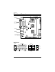
Chapter 1 Mainboard Layout CPU CPUFAN DIMM ATXPWR KBMS Top: Mouse Bottom: Keyboard SYSFAN FDD Top: Parallel Bottom (L): VGA Bottom (R): COM1 PWRFAN I2C FIR COM2 BIOS Socket CLE266 LVDS IDE1 IDE2 Top: RJ45 Bottom: USB USB 5/6 Top: RJ45 Bottom: USB COM4 CMOS Battery Top: Line-in Middle: Line-out Bottom: Microphone CD_IN COM3 CLEAR_CMOS F_AUDIO PCI WOL F_PANEL Back Panel PS2_MS Parallel (LPT1) RJ45 Line-In Line-Out Microphone PS2_KB VGA Out COM1 USB 1-4
Specifications Back Panel Ports Port Audio Jacks COM1 LPT1 PS2-MS PS2-KB RJ45_1 & RJ45_2 USB1, USB2, USB3, & USB4 VGA Out Description Line-Out, Line-In, Microphone Serial port Parallel port PS2 mouse port PS2 keyboard port 10/100 NIC port Universal Serial Bus ports 1 - 4 Page 2-10 2-8 2-9 2-7 2-7 2-8 2-8 VGA out port 2-8 Description Memory module slot Expansion card slot Page 2-4 2-19 Slots Slot DIMM PCI 1-5
Chapter 1 Onboard Connectors and Jumpers Connecter/Jumper ATXPWR CD_IN CLEAR_CMOS COM2, COM3, & COM4 F_AUDIO F_PANEL Fans FDD FIR Description ATX power cable connector Onboard CD audio cable connector Jumper to reset CMOS settings to default Serial port connectors Page 2-6 2-16 2-18 2-15 Front Audio connector (Mic and Line-out) Case connectors CPU, System and Power fans Floppy disk drive connector Infrared Radiation connector I2C IDE1 & IDE2 KBMS LVDS USB 5/6 WOL I2C connector IDE hard disk drive conn
Chapter 2 Installation This chapter provides you with information about hardware setup procedures. While installing the mainboard, carefully hold the components and closely follow the installation procedures. Some components may be damaged if they are installed incorrectly. It is recommended to use a grounded wrist strap before handling computer components. Static electricity can damage some components.
Chapter 2 CPU The VIA EPIA-CL Mini-ITX Mainboard includes an embedded VIA Eden Processor or VIA C3TM E-Series Processor. The CPUFAN (CPU fan) and SYSFAN (system fan) run on +12V and maintain system cooling. When connecting the wire to the connectors, always be aware that the red wire is the Positive and should be connected to the +12V. The black wire is Ground and should be connected to GND. The CPU, System and Power fan connectors have sensors to detect fan speed.
Installation The VIA Eden Processor Providing ultra-low power consumption and advanced thermal dissipation properties, the VIA Eden Processor features a fanless design. The VIA Eden Processor requires only a heatsink as shown. Warning: This motherboard is not designed to support overclocking. Any attempt to operate beyond product specifications is not recommended. We do not guarantee the damages or risks caused by operation beyond product specifications.
Chapter 2 Memory Module Installation The VIA EPIA-CL Mini-ITX Mainboard provides one DIMM slot for DDR266 memory modules. CLE266 DDR Module Installation Procedures 1. Push the white retaining latches at either end of the DIMM slot outwards. 2. Align the DDR module with the corresponding notches on the DIMM slot. The modules will only fit if placed in the correct position. 3.
Installation Available DDR Configurations Refer to the table below for available DDR configurations on the mainboard.
Chapter 2 Connecting the Power Supply The VIA EPIA-CL Mini-ITX Mainboard requires an ATX power supply to be connected. Before inserting the power supply connector, always make sure that all components are installed correctly to ensure that no damage will be caused. ATX 20-Pin Power Connector To connect the ATX power supply, make sure the plugs of the power supply are inserted in the proper orientation and the pins are correctly aligned. Then, push down the power supply plug firmly into the connector.
Installation Back Panel Ports The back panel has the following ports: PS2_MS Parallel (LPT1) RJ45 Line-In Line-Out Microphone PS2_KB VGA Out COM1 USB Mouse Port: PS2_MS The mainboard provides a standard PS/2 mouse connector for attaching a PS/2 mouse. You can plug a PS/2 mouse directly into this connector. The connector location and pin assignments are as follows.
Chapter 2 VGA Out A DB-15 pin female connector that connects to a VGA monitor. Serial Ports: COM1 The mainboard offers one 9-pin male Serial Port connectors COM1. You can attach a serial mouse or other serial devices directly to these ports.
Installation Parallel Port: LPT1 The mainboard provides a 25-pin female connector for LPT (parallel port). A parallel port is a standard printer port that supports Enhanced Parallel Port (EPP) and Extended Capabilities Parallel Port (ECP) modes.
Chapter 2 Audio Jacks: Line-In, Line-Out, Microphone The Line-Out jack is for connecting to external speakers or headphones. The Line-In jack is for connecting to an external audio device such as a CD player, tape player, etc.... The Mic jack is for connecting to a microphone.
Installation Connectors Hard Disk Connectors: IDE1 & IDE2 The mainboard has a 32-bit Enhanced PCI IDE and Ultra DMA 66/100/133 controller that provides PIO mode 0~4, Bus Master, and Ultra DMA 66/100/ 133 functions. You can connect up to four hard disk drive, CD-ROM, LS120 and other devices. These connectors utilize the provided IDE hard disk cable. CLE266 IDE1 IDE2 IDE1 (Primary IDE Connector) The first hard drive should always be connected to IDE1. IDE1 can connect a Master and a Slave drive.
Chapter 2 Case Connectors: F_PANEL The F_PANEL connector block allows you to connect to the power switch, reset switch, power LED, HDD LED, SLED and the Speaker on the case. Pin 1 3 5 7 9 11 13 15 Signal PWR LED+ PWR LED+ PWR LEDSPEAKER+ NC NC SPEAKERNC Pin 2 4 6 8 10 12 14 16 Signal HDD LED+ HDD LEDPW_BN+ PW_BNRESET+ RESETSLP_LED+ SLP_LED- 2 16 1 15 CLE266 Power Switch (PW_BN) Connect to a 2-pin push button switch. Pressing this button will turn the system power on or off.
Installation IrDA Infrared Module Connector: FIR This connector allows you to connect an IrDA Infrared module. You must configure the setting through the BIOS setup to activate the IR function. Pin Signal 1 VCC 2 IRRX1 3 IRRX 4 GND 5 IRTX FIR CLE266 5 1 Consumer Infrared Module / PS2 Header: KBMS When the header is not in use, please short pin 3&5, pin 4&6, pin 7&9, and pin 8&10.
Chapter 2 USB pin-header: USB 5/6 The mainboard provides 1 front USB pin-header connector, allowing up to 2 additional USB ports. Please plug the USB 2-port module onto this pinheader. Pin 1 3 5 7 9 Signal VCC USB2 USB2 + GND NC Pin 2 4 6 8 10 Signal VCC USB 3 USB 3 + GND GND 10 9 2 1 CLE266 USB 5/6 Wake-on LAN: WOL This connector allows you to connect a network card with the Wake-On LAN function. The connector will power up the system when a signal is received through the network card.
Installation Serial Ports: COM2, COM3 and COM4 COM2 is a pin header for second serial port. Pin 1 2 3 4 5 6 7 8 9 Signal DCD SIN SOUT DTR GND DSR RTS CTS RI Description Data Carry Detect Serial In or Receive Data Serial Out or Transmit Data Data Terminal Ready Ground Data Set Ready Request To Send Clear To Send Ring Indicate 9 2 1 COM2 CLE266 FDD 1 2 9 COM4 9 1 2 COM3 Floppy Disk Drive Connector: FDD The floppy disk drive connector supports 360K, 720K, 1.2M. 1.44M, and 2.88M floppy disk types.
Chapter 2 I2C Connector: I2C This is for connecting a I2C device. Pin 1 2 3 4 5 6 Signal +3.3V +3.3V EL-ON SMBCK SMBDT GND 2 IC 6 CLE266 CD_L 2 GND 1 10 GND CD_R 1 CD_IN 9 F_AUDIO CD Audio Connector: CD_IN This connector is for the CD-ROM audio connector. Front Audio Panel: F_AUDIO This connector allows you to connect a front audio panel to the mainboard. Only the line-out and microphone functions are available for use on the front panel.
Installation LVDS Connector (Optional) This connector allows you to connect to a LVDS module. The LVDS connector may not be available on your mainboard. This is an option that is added during the manufacturing process. If you would like a mainboard with the LVDS connector, please contact your vendor or sales contact for more information. Pin 1 3 5 7 9 11 13 15 17 19 21 23 25 27 29 31 33 35 37 39 Signal GFPDE GFPD0 GFPD1 GFPD2 GFPHS GFPVS GFPD11 GFPD12 ENPVDD ENPVEE FPBKLP PWRGD_SB SPCLK2 SPD2 GND GND 3.
Chapter 2 Jumpers The mainboard provides jumpers for setting the mainboard’s functions. This section will explain how to change settings for your mainboard’s functions through the use of the jumpers. Clear CMOS: CLEAR_CMOS The onboard CMOS RAM stores system configuration data and has an onboard battery power supply. The long-life battery has a lifetime of at least 5 years. If you want to clear the system configuration data from the CMOS RAM, use the CLEAR_CMOS (Clear CMOS jumper).
Installation Slots Peripheral Component Interconnect: PCI The PCI slot allows you to insert PCI expansion card. When adding or removing expansion cards, make sure that you unplug the power supply first. Meanwhile, read the documentation for the expansion card to make any necessary hardware or software settings for the expansion card, such as jumpers, switches or BIOS configuration.
Chapter 3 BIOS Setup This chapter gives you detailed explaination of each BIOS setup functions.
Chapter 3 Entering Setup Power on the computer and press Delete straight away to enter the BIOS setup menu. If you missed the BIOS setup entry point, you may restart the system and try again.
BIOS Setup Getting Help Main Menu The main menu displays all BIOS setup categories. Use the control keys Up/Down Arrow Keys to select any item/sub-menu. Description of the selected/highlighted category is displayed at the bottom of the screen. Sub-Menu If you find a right pointer symbol (as shown in IDE Primary Master the right view) appears on the left of certain IDE Primary Slave fields, this means a sub-menu is available. The IDE Secondary Master sub-menu contains additional options.
Chapter 3 The Main Menu The Main Menu contains twelve setup functions and two exit choices. Use arrow keys to select the items and press Enter to accept or enter the submenu. Standard CMOS Features Use this menu to set basic system configurations. Advanced BIOS Features Use this menu to set the advanced features available on your system. Advanced Chipset Features Use this menu to set chipset specific features and optimize system performance.
BIOS Setup Frequency/Voltage Control Use this menu to set the system frequency and voltage control. Load Fail-Safe Defaults Use this menu option to load the BIOS default settings for minimal and stable system operations. Load Optimized Defaults Use this menu option to load BIOS default settings for optimal and high performance system operations. Set Supervisor Password Use this menu option to set the BIOS supervisor password. Set User Password Use this menu option to set the BIOS user password.
Chapter 3 Standard CMOS Features Date The date format is . Day - day of the week, for example Friday. Read-only. Month - the month from Jan to Dec. Date - the date from 1 to 31. Year - the year, range from 1999 to 2098. Time The time format is . Drive A/B Set the type of floppy drive installed. Settings: None, 360K (5.25 in.), 1.2M (5.25 in.), 720K (3.5 in.), 1.44M (3.5 in.), 2.88M (3.5 in.
BIOS Setup IDE Primary Master/Slave, Secondary Master/Slave Press Enter to enter the sub-menu and the following screen appears: The specifications of your drive must match with the drive table. The hard disk will not work properly if you enter improper information for this category. Select Auto whenever possible. If you select Manual, make sure the information provided is from your hard disk vendor or system manufacturer.
Chapter 3 Advanced BIOS Features Virus Warning Set the Virus Warning feature for IDE Hard Disk boot sector protection. If the function is enabled, any attempt to write data into this area will cause a beep and warning message display on screen. Settings: Disabled and Enabled CPU L2 Cache ECC Checking Set the ECC (Error-Correcting Code) feature for Level 2 cache. Facilitates error detection/correction when data passes through Level 2 cache.
BIOS Setup First/Second/Third Boot Device Set the boot device sequence as BIOS attempts to load the disk operating system. The settings are: Floppy LS120 HDD-0 SCSI CD-ROM HDD-1 HDD-2 HDD-3 ZIP100 USB-FDD USB-ZIP USB-CDROM USB-HDD LAN Disabled The system will boot from floppy drive. The system will boot from LS-120 drive. The system will boot from first HDD. The system will boot from SCSI. The system will boot from CD-ROM. The system will boot from second HDD. The system will boot from third HDD.
Chapter 3 Boot Up NumLock Status Set the NumLock status when the system is powered on. On will turn key pad into number keys, and Off will turn key pad into arrow keys. Settings: On and Off Typematic Rate Setting When Disabled, the following two items (Typematic Rate and Typematic Delay) are irrelevant. Keystrokes repeat at a rate determined by the keyboard controller in your system. When Enabled, you can select a typematic rate and typematic delay.
BIOS Setup Show Summary Information Settings: Enabled and Disabled Display Small Logo Show small energy star logo during BIOS bootup process.
Chapter 3 Advanced Chipset Features The Advanced Chipset Features menu is used for optimizing the chipset functions. WARNING: Do not change these settings unless you are familiar with the chipset. AGP Aperture Size This setting controls how much memory space can be allocated to AGP for video purposes. The aperture is a portion of the PCI memory address range dedicated to graphics memory address space. Host cycles that hit the aperture range are forwarded to the AGP without any translation.
BIOS Setup CPU to PCI POST Write When Enabled, CPU can write up to four words of data to the PCI write buffer before CPU must wait for PCI bus cycle to finish. If Disabled, CPU must wait after each write cycle until PCI bus signals that it is ready to receive more data. Settings: Enabled and Disabled Select Display Device This setting refers to the type of display being used with the system.
Chapter 3 Integrated Peripherals Onboard IDE Channel 1/2 The integrated peripheral controller contains an IDE interface with support for two IDE channels. Choose Enabled to activate each channel separately. Settings: Enabled and Disabled IDE Prefetch Mode This allows your hard disk controller to use the fast block mode to transfer data to and from the hard disk drive. Block mode is also called block transfer, multiple commands or multiple sector read/write.
BIOS Setup AC97 Audio Auto allows the mainboard to detect whether an audio device is used. If the device is detected, the onboard VIA AC’97 (Audio Codec’97) controller will be enabled; if not, it is disabled. Disable the controller if you want to use other controller cards to connect to an audio device. Settings: Auto and Disabled VIA OnChip LAN This setting allows you to make VIA OnChip LAN enabled or disabled.
Chapter 3 SuperIO Device Press Enter to enter the sub-menu and the following screen appears: Onboard FDC Controller Enable the onboard floppy controller. Select Enabled when you have installed a floppy disk drive. Settings: Enabled, Disabled Onboard Serial Port 1/2/3/4 Set the base I/O port address and IRQ for the onboard serial port A/serial port B. Selecting Auto allows BIOS to automatically determine the correct base I/O port address.
BIOS Setup Parallel Port Mode Set the parallel port mode. To operate the onboard parallel port as Standard Parallel Port, choose SPP. To operate the onboard parallel port in the EPP mode, choose EPP. By choosing ECP, the onboard parallel port will operate in ECP mode. Choosing ECP + EPP will allow the onboard parallel port to support both the ECP and EPP modes simultaneously. Settings: SPP, EPP, ECP, ECP + EPP EPP Mode Select EPP (Enhanced Parallel Port) comes in two modes: 1.9 and 1.7. EPP 1.
Chapter 3 Power Management Setup The Power Management Setup menu configures the system to most effectively save energy while operating in a manner consistent with your own style of computer use. ACPI Suspend Type Set the power saving mode for ACPI function. Settings are: S1(POS) S3(STR) S1 & S3 S1/Power On Suspend (POS) is a low power state. In this state, no system context (CPU or chipset) is lost and hardware maintains all system context. S3/Suspend To RAM (STR) is a power-down state.
BIOS Setup Power Management Timer Set the idle time before system enters power saving mode. ACPI OS such as Windows XP will override this option. Settings: Disabled and 1/2/4/6/8/10/20/ 30/40 (minutes) and 1 (hour) Video Off Option Select whether or not to turn off the screen when system enters power saving mode, ACPI OS such as Windows XP will override this option. Settings are: Always On Suspend -> Off The screen is always on even when system enters power saving mode.
Chapter 3 Peripheral Activities Press Enter to enter the sub-menu and the following screen appears: VGA Event Decide whether or not the power management unit should monitor VGA activities. Settings: Off and On LPT & COM Event Decide whether or not the power management unit should monitor parallel port (LPT) and serial port (COM) activities. Settings: None, LPT, COM and LPT/COM HDD & FDD Event Decide whether or not the power management unit should monitor hard disks and floppy drives activities.
BIOS Setup PS2MS Wakeup from S3/S4/S5 This setting can be used to wakeup the system from power saving mode through mouse. Settings: Disabled and Enabled PS2KB Wakeup from S3/S4/S5 Select which Hot-Key to wake-up the system from power saving mode. Settings: Disabled, Ctrl+F1, Ctrl+F2, Ctrl+F3, Ctrl+F4, Ctrl+F5, Ctrl+F6, Ctrl+F7, Ctrl+F8, Ctrl+F9, Ctrl+F10, Ctrl+F11, Ctrl+F12, Power, Wake and Any Key USB Resume Decide whether or not USB devices can wake the system from suspend state.
Chapter 3 IRQs Activities Press Enter to enter the sub-menu and the following screen appears: Primary INTR Selecting On will cause the system to wake up from power saving modes if activity is detected from any enabled IRQ channels. Settings: Off, On IRQ3~IRQ15 Enables or disables the monitoring of the specified IRQ line. If set to Enabled, the activity of the specified IRQ line will prevent the system from entering power saving modes or awaken it from power saving modes.
BIOS Setup PNP/PCI Configurations This section describes the BIOS configuration of the PCI bus system. This section covers some very technical items and it is strongly recommended that only experienced users should make any changes to the default settings. PNP OS Installed When set to Yes, BIOS will only initialize the PnP cards used for booting (VGA, IDE, SCSI). The rest of the cards will be initialized by the PnP operating system like Windows 95 or 98/98SE.
Chapter 3 Assign IRQ For VGA/USB Assign IRQ for VGA and USB devices.
BIOS Setup IRQ Resources The items are adjustable only when Resources Controlled By is set to Manual. Press Enter and you will enter the sub-menu of the items. IRQ Resources list IRQ 3/4/5/7/9/10/11/12/14/15 for users to set each IRQ a type depending on the type of device using the IRQ. Settings: PCI Device Reserved For Plug & Play compatible devices designed for PCI bus architecture. The IRQ will be reserved for further request.
Chapter 3 PC Health Status This section shows the status of your CPU, fan, warning for overall system status. The PC Health Status displays the current status of all of the monitored hardware devices/components such as CPU voltages, temperatures and fan speeds.
BIOS Setup Frequency / Voltage Control DRAM Clock The chipset supports synchronous and asynchronous mode between host clock and DRAM clock frequency. Settings: 66 MHz, 100 MHz, 133 MHz, and By SPD DRAM Timing The value in this field depends on the memory modules installed in your system. Changing the value from the factory setting is not recommended unless you install new memory that has a different performance rating than the original modules.
Chapter 3 Bank Interleave Set the interleave mode of the SDRAM interface. Interleaving allows banks of SDRAM to alternate their refresh and access cycles. One bank will undergo its refresh cycle while another is being accessed. This improves performance of the SDRAM by masking the refresh time of each bank. This field is only available when DRAM Timing is set to Manual.
BIOS Setup DRAM Voltage This field sets the voltage for the memory module. Settings: 2.9V, 2.8V, 2.6V, 2.5V Spread Spectrum When the mainboard’s clock generator pulses, the extreme values (spikes) of the pulses creates EMI (Electromagnetic Interference). The Spread Spectrum function reduces the EMI generated by modulating the pulses so that the spikes of the pulses are reduced to flatter curves.
Chapter 3 Load Fail-Safe Defaults This option on the main menu allows users to restore all the BIOS settings to the default Fail Safe values. These values are set by the mainboard manufacturer to provide a minimal and stable system. When you select Load-Fail Safe Defaults, a message as below appears: Entering Y loads the default BIOS values that provide a minimal and stable system configuration.
BIOS Setup Load Optimized Defaults This option on the main menu allows users to restore all the BIOS settings to the default Optimized values. The Optimized Defaults are the default values also set by the mainboard manufacturer for both optimized and stable performance of the mainboard. When you select Load Optimized Defaults, a message as below appears: Entering Y loads the default values that are factory settings for optimal and stable system performance.
Chapter 3 Set Supervisor / User Password When you select this function, a message as below will appear on the screen: Type the password, up to eight characters in length, and press Enter. The password typed now will clear any previously set password from CMOS memory. You will be prompted to confirm the password. Re-type the password and press Enter. You may also press Esc to abort the selection and not enter a password. To clear a set password, just press Enter when you are prompted to enter the password.
BIOS Setup Additionally, when a password is enabled, you can also have BIOS to request a password each time the system is booted. This would prevent unauthorized use of your computer. The setting to determine when the password prompt is required is the Security Option of the Advanced BIOS Features menu. If the Security Option is set to System, the password is required both at boot and at entry to Setup. If set to Setup, password prompt only occurs when trying to enter Setup.
Chapter 3 Save & Exit Setup When you want to quit the Setup menu, you can select this option to save the changes and quit. A message as below will appear on the screen: Entering Y will allow you to quit the Setup Utility and save the user setup changes to RTC CMOS. Entering N will return to the Setup Utility.
BIOS Setup Exit Without Saving When you want to quit the Setup menu, you can select this option to abandon the changes. A message as below will appear on the screen: Entering Y will allow you to quit the Setup Utility without saving any changes to RTC CMOS. Entering N will return to the Setup Utility.
Chapter 4 Driver Installation This chapter gives you brief descriptions of each mainboard drivers and applications. You must install VIA chipset drivers first before installing other drivers such as audio or VGA drivers. The applications will only function correctly if the necessary drivers are already installed.
Chapter 4 Driver Utilities Getting Started The mainboard includes a Driver Utilities CD which contains driver utilities and software to enhance the performance of the mainboard. Please check that you have this CD in your retail box. If the CD is missing in your retail box, please contact your local dealer for the CD. Note: The driver utilities and software are updated from time to time. Please visit our website (http://www.viaembedded.com/) for the latest updated mainboard driver and utilities.
Driver Installation CD Content The driver utilities and software in this CD are: • VIA 4in1 Drivers: Contains VIA ATAPI Vendor Support Driver (enables the performance enhancing bus mastering functions on ATAcapable Hard Disk Drives and ensures IDE device compatibility), AGP VxD Driver (provides service routines to your VGA driver and interface directly to hardware, providing fast graphical access), IRQ Routing Miniport Driver (sets the system’s PCI IRQ routing sequence) and VIA INF Driver (enables the VIA