
Programming instructions

line follower kit • 2
Inventor’s Guide insert
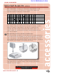
accessories
sensor accessories
accessories
line follower kit, continued
Course correction
based on sensor
reading
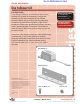
1 Technical overview
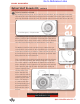
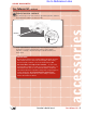
This is an analog sensor, meaning that its output covers a range of values
(in this case, from zero to five volts) rather than being only high (five volts)
or low (zero volts), as is the case for a digital sensor. This range of output
from zero to five volts is sent to the microcontroller, which reads it as a range
of integer values from 0 to 255. [For more detail, refer to the Sensors chapter
in your Vex Inventor’s Guide.]
For this particular sensor, sensor output will be low (around 0) when the infrared
light bounces back to the detector – in other words, when the surface is pale or
highly reflective – and high (around 255) when the light is absorbed and does not
bounce back.
We can then set a threshold value in our code to act as a trigger for behaviors.
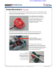
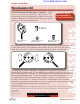
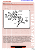
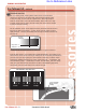
From this basic premise, we can build more complicated behaviors. For example, if you
have three line sensors on the front of your robot [hint: use the mounting bar included in
your kit!], then you can program your robot to follow a white line on a black surface.
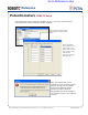
LineFollower_Middle should always see white, and the other two — LineFollower_Left
and LineFollower_Right — should always see black. If LineFollower_Left starts seeing
white, then your robot needs to steer back to the left. If LineFollower_Right starts
seeing white, then your robot needs to steer back to the right.
Maximum
Illumination
Minimum
Illumination
0V
5V
Analog Value =
0
255
Integer V
alue =
0 255 255 255 0 255 255 255 0
line on left
steer left
line in middle
steer straight
line on right
steer right
Line followers, top down view
Go to Reference Links