
Programming instructions

accessories
sensor accessories
Potentiometer Kit, continued
Potentiometer Kit • 2
For More Information, and additional Parts & Pieces refer to:
www.VexRobotics.com
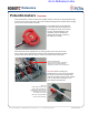
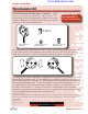
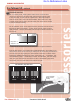
Slide the Potentiometer down the shaft being measured, and ensure that it sticks out of
the Potentiometer a little bit on the far side. Mount the Potentiometer using the provided
hardware. Ensure the Potentiometer is centered on the shaft and that there is no mechanical
bind BEFORE tightening the mounting screws.
The Potentiometer (or Pot for short) describes an electrical device in which the user can
adjust the resistance. As the resistance of the sensor changes, a varying voltage is created
and thus the sensor acts as a variable voltage divider. This varying analog voltage can be
measured by the Vex Controller and is proportional to the position of the shaft connected
to the center of the Pot. This is how you obtain an analog measurement of an angular
position.
Before you can use the Potentiometer, you must reprogram your Vex Controller to read
the varying voltage of the sensor on the corresponding port you are planning on connecting
to. How to write/change your code to read the varying voltage is not covered in these
instructions. We suggest searching our Forum for help at www.vexforum.com. To connect
the Potentiometer Sensor to the Vex Controller, you plug the Sensor Connector into any
port in the Analog/Digital Bank on the Vex Controller, typically you start with the 1st
position. Note that the Connector is keyed to fit into the Vex Controller Port in a specific
orientation; plugging it in backwards could damage your Sensor.
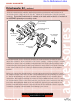
Robot Structure
(not included)
Shaft being measured
(not included)
1/2” Mounting
Screw (2x)
Potentiometer
Assembly
1/2” Threaded
Beam (2x)
1/4” Mounting
Screw (2x)
Go to Reference Links