Robotics Reference Guide Version 2.0 This guide undergoes continuous revision, including the addition of more reference guides. Be sure to visit the engineering section of the Virtual Academy to ensure that you have the most recent version. To determine whether you have the most up-to-date version, reference the date in the filename.
Robotics Reference Guide Reference Links Each Reference below is a link to that file.
Go to Reference Links Robotics Reference Guide Reference Links Each Reference below is a link to that file.
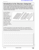
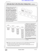
Structure Go to Reference Links Introduction to the Structure Subsystem The parts in the VEX Structure Subsystem form the base of every robot. These parts are the “skeleton” of the robot to which all other parts are attached. This subsystem consists of all the main structural components in the VEX Design System including all the metal components and hardware pieces. These pieces connect together to form the “skeleton” or frame of the robot.
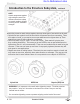
Structure Go to Reference Links Introduction to the Structure Subsystem, continued VEX square holes are also used as “alignment features” on some components. These pieces will “snap” in place into these square holes. For example, when mounting a VEX Bearing Flat there are small tabs which will stick through the square hole and hold it perfectly in alignment. This allows for good placement of components with key alignment requirements.
Go to Reference Links Structure Introduction to the Structure Subsystem, continued HINT: Attach components together with multiple screws from different directions to keep structural members aligned correctly and for maximum strength! When using screws to attach things together, there are three types of nuts which can be used. • Nylock nuts have a plastic insert in them which will prevent them from unscrewing. These are harder to install, as you need to use an open-ended wrench to tighten them up.
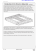
Structure Go to Reference Links Introduction to the Structure Subsystem, continued Components can also be offset from each other using 8-32 threaded standoffs; these standoffs come in a variety of lengths and add great versatility to the VEX kit. These standoffs work great for mounting components in the VEX system as well as for creating structural beams of great strength. One of the key features of many VEX structural parts is their “bend-able” and “cut-able” nature.
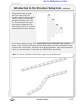
Structure Go to Reference Links Introduction to the Structure Subsystem, continued The VEX structural components come in a variety of shapes and sizes. Each of these structural shapes may be strong in some ways but weak in others. It is very easy to bend a piece of VEX Bar in one orientation, but it is almost impossible to bend it when it is in another orientation. Applying this type of knowledge is the basis of structural engineering.
Go to Reference Links Structure Concepts to Understand, continued Robust Fabrication Fasteners The most common problem with robots that fall apart or lose pieces easily is that groups of parts are not joined securely enough and separate from each other and move around. EXAMPLE 1: Arm Extension A robot needs to be able to reach a goal that is high off the ground. The goal is so high that a single long piece will not reach it. Two pieces must be joined together to reach the desired height.
Structure Go to Reference Links Concepts to Understand, continued Robust Fabrication, continued EXAMPLE 1, continued: Arm Extension, continued By using two screws, this design removes the possibility of rotation around either one of them. Additionally, the design is more resilient.
Go to Reference Links Structure Concepts to Understand, continued Robust Fabrication, continued EXAMPLE 2: Bracing The extended bars are now attached firmly to each other, and the long arm is mounted on your robot. However, the long arm is going to generate huge stresses at its mounting point because it is so long, especially when the arm is used to lift a load.
Go to Reference Links Structure Concepts to Understand, continued Robust Fabrication, continued EXAMPLE 2: Bracing the Bars, continued In order to keep the arm from falling down, you will need to brace it. You could use a second screw to hold it, like you did with the arm itself, but because the arm is such a long lever arm, that screw would actually be in danger of deforming or breaking.
Go to Reference Links Motion Introduction to the Motion Subsystem The Motion Subsystem comprises all the components in the VEX Robotics Design System which make a robot move. These components are critical to every robot. The Motion Subsystem is tightly integrated with the components of the Structure Subsystem in almost all robot designs. In the VEX Robotics Design System the motion components are all easily integrated together.
Go to Reference Links Motion Introduction to the Motion Subsystem, continued Another type of bearing used in the VEX Motion Subsystem is a Bearing Block; these are similar to the “pillowblocks” used in industry. The Bearing Block mounts on a piece of structure and supports a shaft which is offset either above, below, or to the side of the structure. 276-2178-E-0610 Some bearings can be mounted to VEX structural components with Bearing Pop Rivets. These rivets are pressed into place for quick mounting.
Go to Reference Links Motion Introduction to the Motion Subsystem, continued The key component of any motion system is an actuator (an actuator is something which causes a mechanical system to move). In the VEX Robotics Design System, there are several different actuator options. The most common types of actuators used are the VEX Continuous Rotation Motors (the 3-Wire Motor and the “high strength” 2-Wire Motor 393) and the VEX Servos.
Go to Reference Links Motion Introduction to the Motion Subsystem, continued In some applications excessive loads can damage the components of the VEX Motion Subsystem. In these cases there are often ways to reinforce the system to reduce the load each individual component will experience, or so that the load is no longer concentrated at a single location on any given component. Gear Train 1 EXAMPLE: One example of a component failure is fracturing gear teeth.
Go to Reference Links Motion Introduction to the Motion Subsystem, continued It is easy to drive components of the VEX Structure Subsystem using motion components in several different ways. Most of the VEX Gears have mounting holes in them on the standard VEX 1/2” hole spacing; it is simple to attach metal pieces to these mounting holes.
Motion Go to Reference Links Introduction to the Motion Subsystem, continued The VEX Motion Subsystem contains a variety of components designed to help make robots mobile. This includes a variety of wheel sizes, tank treads, and other options. Robots using these in different configurations will have greatly varying performance characteristics. Tank Tread components and wheels can also be used to construct intake mechanisms and conveyor belts. These are frequently used on competition robots.
Go to Reference Links Reference Cortex Pin Guide The VEX Cortex Microcontroller coordinates the flow of all information and power on the robot. It has built in bidirectional communication for wireless driving, debugging and downloading using the state of the art VEXnet 802.11 wireless link. The Microcontroller is the brain of every VEX robot. Analog Outputs & Digital Inputs / Outputs: Motor Outputs: • Analog Outputs are used by any sensors that provide a range of values.
Go to Reference Links Reference VEX Cortex Configuration over USB The VEX Cortex is a fully programmable device, and is what enables you to incorporate motors, sensors, an LCD screen, and remote control signals all in one robot. Inside of the Cortex, there are two separate processors; a user processor handles all of the ROBOTC programming instructions, and a master processor controls lower-level operations, like motor control and VEXnet communication.
Go to Reference Links Reference VEX Cortex Configuration over USB (cont.) 2. Specify that you are using the Cortex and how it is connected to your computer in ROBOTC. 2a. Detailed Preferences... Go to View > Preferences and select Detailed Preferences... 2b. Platform Settings Make sure that the Platform tab is selected on the ROBOTC Preferences window. Next, specify the Natural Language (VEX Cortex) as your Platform Type.
Go to Reference Links Reference VEX Cortex Configuration over USB (cont.) 3. The VEX Cortex Download Method controls how ROBOTC downloads firmware and programs to your Cortex, as well as what types of connections your Cortex checks for when it is powered on. Confirm that your VEX Cortex Download Method is set to Download Using VEXnet or USB or Download Using USB Only.
Go to Reference Links Reference VEX Cortex Configuration over USB (cont.) 4. Go to Robot > Download Firmware > Master CPU Firmware and select Standard File to download the latest Master CPU Firmware to your robot. 4. Download Progress A Download Progress window will appear and begin the download process. When the window closes, the firmware download is complete. A ROBOTC Message will appear, and remind you to also download the ROBOTC Firmware.
Go to Reference Links Reference VEX Cortex Configuration over USB (cont.) 5. The ROBOTC Firmware enables you to download ROBOTC programs to your robot and utilize the various debug windows. Go to Robot > Download Firmware > ROBOTC Firmware and select Standard File to download the ROBOTC Firmware to your robot. 5. Download Progress A Download Progress window will appear and begin the download process. When the window closes, the firmware download is complete.
Go to Reference Links Reference Using the PLTW Template The PLTW template is the starting point for all your programs. The template is located in the Sample Programs in the PLTW folder. Before typing in the template you MUST go to File, Save As, then navigate to the folder to save your robotics projects in, appropriately name your program, and click Save. All Robotics Projects should be completed using the PLTW template. Open the PLTW folder in Sample Programs to get the PLTWtemplate file.
Go to Reference Links Reference Using the PLTW Template The commented section above task main provides an are to coplete your identification information date, a narrative of what the program will and a place for pseudocode. ROBOTC uses different colors to help identify code and text. This makes it easy to navigate through the program in addition to providing clues about mistakes when items are a different color than expected.
Go to Reference Links Reference Sample Programs One of the easiest ways to begin programming is to start with existing code, try it out, and then modify it. ROBOTC includes over 70 sample programs to help you get started with learning how to program. To open a sample program, go to the File menu and select Open Sample Program. All of the ROBOTC sample programs have “comments” that tell how the robot should be configured, and To access Sample Programs go File > Open Sample Programs.
Go to Reference Links Reference Running a Program Once a program has been successfully written, it needs to be given to the robot to run. The following steps will guide you through the process of downloading your program to the robot, and then running it remotely or connected to your computer. 1. Make sure your VEX is turned on. Move the switch from the OFF position to the ON position. 2. Make sure your robot is plugged in to the computer via the Programming Module.
Go to Reference Links Reference VEXnet Joystick Configuration in ROBOTC The VEXnet Joystick enables more than just the remote control of your robot. It also provides the wireless communication link between your computer and the VEX Cortex, enabling you to wirelessly download firmware, programs and run the ROBOTC debugger. In this document, you will learn how to configure VEXnet Joystick using ROBOTC. This document is broken into 3 sections: 1. Downloading Firmware to the VEXnet Joystick 2.
Go to Reference Links Reference VEXnet Joystick Configuration in ROBOTC (cont.) 2. Connect the VEXnet Joystick to your computer using the USB A-to-A cable and turn it ON. 2a. Connect the VEXnet Joystick Use the USB A-to-A cable to connect your VEXnet Joystick to your computer. Note: The VEXnet light should turn green. 2b. Turn the VEXnet Joystick ON Switch the VEXnet Joystick to the ON postion. Note: The Joystick light should turn green.
Go to Reference Links Reference VEXnet Joystick Configuration in ROBOTC (cont.) 3. Go to Robot > Download Firmware > VEXnet Joystick Firmware and select Standard File to download the latest VEXnet Joystick Firmware to the controller. 3. Download Progress A Download Progress window will appear and begin the download process. When the window closes, the firmware download is complete.
Go to Reference Links Reference VEXnet Joystick Configuration in ROBOTC (cont.) Section 2: Creating a wireless link betwen the VEXnet Joystick and VEX Cortex In this section, you will learn how to pair a VEX Cortex Microcontroller to a VEXnet Joystick, allowing them to communicate over VEXnet. This section assumes that you have already updated the master firmware on the VEX Cortex and VEXnet Remote Control. VEXnet is an 802.11 WiFi communication system between the VEX Cortex and VEXnet Remote Control.
Go to Reference Links Reference VEXnet Joystick Configuration in ROBOTC (cont.) 2. Tether the USB port on the VEXnet Joystick to the USB port on the Cortex using a USB A-to-A cable. 2a. VEXnet Joystick USB Port Plug one end of the USB A-to-A cable into the USB port on the VEXnet Joystick. 2b. VEX Cortex USB Port Plug the other end of the USB A-to-A cable into the USB port on the VEX Cortex. 3. Power the Cortex ON.
Go to Reference Links Reference VEXnet Joystick Configuration in ROBOTC (cont.) 4. Turn the Cortex OFF. 5. Remove the USB A-to-A cable from the VEXnet Joystick and Cortex. 6. Insert VEXnet USB Keys into both the VEXnet Joystick and Cortex. 6. VEXnet USB Keys Insert VEXnet USB Keys into the VEXnet Joystick and Cortex. Note: It does not matter which VEXnet USB Key you insert into the Cortex versus the VEXnet Joystick.
Go to Reference Links Reference VEXnet Joystick Configuration in ROBOTC (cont.) 7. Power the Cortex and Joystick ON. After roughly 15 seconds, the ROBOT and VEXnet LED’s will blink green, indicating that the VEXnet communication link has been established. 7a. Turn the Cortex ON 7b. Turn the VEXnet Joystick ON 7c. Status LEDs After roughly 15 seconds, the ROBOT and VEXnet status LEDs will start quickly blinking green.
Go to Reference Links Reference VEXnet Joystick Configuration in ROBOTC (cont.) Section 3: Calibrating the VEXnet Joystick Values This section contains the procedure for calibrating the VEXnet Remote Control joysticks. Some steps are time-sensitive, so it’s recommended that you read through the instructions once before following along. The VEXnet Remote Control includes two joysticks (each having an X and Y-axis), 8 buttons on the front, and 4 additional trigger buttons on the top.
Go to Reference Links Reference VEXnet Joystick Configuration in ROBOTC (cont.) 2. Press and hold the 6U trigger button. 2. Press and hold the 6U trigger button 3. While keeping the 6U trigger button pressed in, use your Allen wrench or paper clip to press in the internal CONFIG button until the JOYSTICK LED blinks red and green. 3a. Press and the CONFIG button While still pressing in the 6U trigger button, use an Allen wrench or paper clip to press in the CONFIG button. 3b.
Go to Reference Links Reference VEXnet Joystick Configuration in ROBOTC (cont.) Important - Time Sensitive Instructions There is a 10 second time limit to complete steps 4 and 5. If they are not completed in time, the calibration process will timeout and the VEXnet LED will blink red briefly. 4. Move both joysticks through their full ranges of motion. When the remote control detects that the joysticks have been fully rotated, the JOYSTICK LED stops blinking red and green, and switches to a solid green.
Go to Reference Links Reference VEXnet Joystick Configuration in ROBOTC (cont.) 5. Press the 8U button to save the new calibration. 5. Save Press the 8U button to save the joystick calibration on your remote control. The JOYSTICK LED will blink green for a few seconds. Additional Information • If the calibration is not saved, the process will timeout after 10 seconds and the VEXnet LED will blink red. • To cancel a calibration, press the 7U button.
Go to Reference Links Reference VEXnet Joystick Configuration in ROBOTC (cont.) Troubleshooting Issue: Slow blinking green ROBOT light on the Cortex Solution: Download the Cortex Master Firmware using ROBOTC. Issue: Slow blinking ROBOT green light on the VEXnet Joystick Solution: Push and hold CONFIG button for about 5 seconds, until the status LEDs starts blinking green. Release it, wait for another 5 seconds, and then turn the VEXnet Joystick OFF and then back ON.
Go to Reference Links Reference Sense Plan Act (SPA) Sense, Plan, Act was an early robot control procedure commonly abbreviated SPA. Today we use its fundamental concepts to remind us of the three critical capabilities that every robot must have in order to operate effectively: SENSE: The robot needs the ability to sense important things about its environment, like the presence of obstacles or navigation aids.
Go to Reference Links Reference Boolean Logic Truth Values Robots don’t like ambiguity when making decisions. They need to know, very clearly, which choice to make under what circumstances. As a consequence, their decisions are always based on the answers to questions which have only two possible answers: yes or no, true or false. Statements that can be only true or false are called Boolean statements, and their true-or-false value is called a truth value.
Go to Reference Links Reference Boolean Logic Comparison Operators Comparisons (such as the comparison of the Ultrasonic sensor’s value against the number 45) are at the core of the decision-making process. A well-formed comparison typically uses one of a very specific set of operators, the “comparison operations” which generate a true or false result. Here are some of the most common ones recognized by ROBOTC.
Go to Reference Links Reference Boolean Logic Use in Control Structures “Under the hood” of all the major decision-making control structures is a simple check for the Boolean value of the (condition). The line if (SensorValue(bumper) == 1)... may read easily as “if the bumper switch is pressed, do...”, but the robot is really looking for if(true) or if(false).
Go to Reference Links Reference Variables Variables are places to store values (such as sensor readings) for later use, or for use in calculations. There are three main steps involved in using a variable: 1. Introduce (create or “declare”) the variable 2. Give (“assign”) the variable a value 3.
Go to Reference Links Reference Variables Declaration Rules In order to declare a variable, you must declare its type, followed by its name. Here are some specifics about the rules governing each: Rules for Variable Types • You must choose a data type that is appropriate for the value you want to store The following is a list of data types most commonly used in ROBOTC: Data Type Description Example Code Integer Positive and negative whole numbers, as well as zero. -35, -1, 0, 33, 100, 345 int -.
Go to Reference Links Reference Variables Assignment and Usage Rules Assignment of values to variables is pretty straightforward, as is the use of a variable in a command where you wish its value to be used.
Go to Reference Links Reference Reserved Words Motors Motor control and some fine-tuning commands. motor[output] = power; This turns the referenced VEX motor output either on or off and simultaneously sets its power level. The VEX has 8 motor outputs: port1, port2... up to port8. The VEX supports power levels from -127 (full reverse) to 127 (full forward).
Go to Reference Links Reference Reserved Words wait10Msec(wait_time); This code will cause the robot to wait a specified number of hundredths of seconds before executing the next instruction in a program. “wait_time” is an integer value (where 1 = 1/100th of a second). Maximum wait_time is 32768, or 327.68 seconds.
Go to Reference Links Reference Reserved Words ClearTimer(timer); This resets the referenced timer back to zero seconds. The VEX has 4 internal timers: T1, T2, T3, and T4 ClearTimer(T1); //Clear Timer #1 SensorValue(sensor_input) SensorValue is used to reference the integer value of the specified sensor port. Values will correspond to the type of sensor set for that port. The VEX has 16 analog/digital inputs: in1, in2...
Go to Reference Links Reference Reserved Words Radio Control ROBOTC allows you to control your robot using input from the Radio Control Transmitter. bVexAutonomousMode Set the value to either 0 for radio enabled or 1 for radio disabled (autonomous mode). You can also use “true” for 1 and “false” for 0. bVexAutonomousMode = 0; bVexAutonomousMode = 1; //enable radio control //disable radio control vexRT[joystick_channel] This command retrieves the value of the specified channel being transmitted.
Go to Reference Links Reference Reserved Words Miscellaneous Miscellaneous useful commands that are not part of the standard C language. srand(seed); Defines the integer value of the “seed” used in the random() command to generate a random number. This command is optional when using the random() command, and will cause the same sequence of numbers to be generated each time that the program is run.
Go to Reference Links Reference Reserved Words Data Types Different types of information require different types of variables to hold them. int This data type is used to store integer values ranging from -32768 to 32768. int x; //Declares the integer variable x x = 765; //Stores 765 inside of x The code above can also be written: int x = 765; //Declares the integer variable x and... //...
Go to Reference Links Reference While Loops with Natural Language A while loop is a structure within ROBOTC which allows a section of code to be repeated as long as a certain condition remains true. There are three main parts to every while loop. Part 1. The keyword “while”. while(condition) { // repeated-commands } while Every while loop begins with the keyword “while”. Part 2. The condition.
Go to Reference Links Reference While Loops with Natural Language Below is an example of a program using a counter-controlled While Loop. task main() { int count = 0; Creates an integer variable named “count” and gives it an initial value of 0. Checks if count is “less than” 4. while(count < 4) { startMotor(port2, 63); wait(5.0); startMotor(port2, -63); wait(5.0); Adds 1 to count every time the loop runs.
Go to Reference Links Reference if Statements with Natural Language An if Statement allows your robot to make a decision. When your robot reaches an if Statment in the program, it evaluates the condition contained between the parenthesis. If the condition is true, any commands between the braces are run.
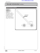
Go to Reference Links Reference if-else Statements with Natural Language The if-else Statement is an expansion of the basic if Statement. The “if” section still checks the condition and runs the appropriate commands when it evaluates to true, but using the “else” allows for specific code to be run only when the condition is false. Pseudocode of an if-else Statment: if(condition) { // true-commands } else { // false-commands } (condition) Either true or false.
Go to Reference Links Reference Embedded if/if-else Statements with Natural Language Sometimes, especially with more complex tasks, your robot will have to make multiple consecutive decisions before performing a behavior. This can be accomplished by embedding, or placing, if Statments within other if Statements.
Go to Reference Links Reference Variables with Natural Language Variables are places to store values (such as sensor readings) for later use, or for use in calculations. There are three main steps involved in using a variable: 1. Introduce (create or “declare”) the variable 2. Give (“assign”) the variable a value 3. Use the variable to access the stored value task main() { int speed; speed = 75; startMotor(port3,speed); startMotor(port2,speed); wait1(2.
Go to Reference Links Reference Variables with Natural Language Declaration Rules In order to declare a variable, you must declare its type, followed by its name. Here are some specifics about the rules governing each: Rules for Variable Types • You must choose a data type that is appropriate for the value you want to store The following is a list of data types most commonly used in ROBOTC: Data Type Description Example Values Code Integer Positive and negative whole numbers, as well as zero.
Go to Reference Links Reference Variables with Natural Language Assignment and Usage Rules Assignment of values to variables is pretty straightforward, as is the use of a variable in a command where you wish its value to be used.
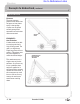
Go to Reference Links Reference Thresholds with Natural Language Thresholds are values that set a cutoff in a range of values, so that even if there are many possibilities, the value eventually falls above the threshold, or below the threshold. Using thresholds allows you to perform certain behaviors depending on where a certain value (usually a sensor value) falls in relation to the threshold. Threshold = 25 cm Near Far If you look at this image, it shows an VEX using an Ultrasonic Rangefinder.
Go to Reference Links Reference Timers Timers are very useful for performing a more complex behavior for a certain period of time. Wait states (from wait1Msec) don’t let the robot execute commands during the waiting period, which is fine for simple behaviors like moving forward. If calculations or other actions need to occur during the timed period, as with the line tracking behavior below, a Timer must be used.
Go to Reference Links Reference Behaviors A behavior is anything your robot does: turning on a single motor is a behavior, moving forward is a behavior, tracking a line is a behavior, navigating a maze is a behavior. There are three main types of behaviors that we are concerned with: basic behaviors, simple behaviors, and complex behaviors.
Go to Reference Links Reference Behaviors Composition and Analysis Perhaps the most important idea in behaviors is that they can be built up or broken down into other behaviors. Complex behaviors, like going through a maze, can always be broken down into smaller, simpler behaviors. These in turn can be broken down further and further until you reach simple or basic behaviors that you recognize and can program.
Go to Reference Links Reference Functions with Natural Language A function is a group of statements that are run as a single unit when the function is called from another location, such as task main(). Commonly, each function will represent a specific behavior in the program. Functions offer a number of distinct advantages over basic step-by-step coding.
Go to Reference Links Reference Advanced Functions Parameters Parameters are a way of passing information into a function, allowing the function to run its commands differently, depending on the values it is given. It may help to think of the parameters as placeholders – all parameters must be filled in with real values when the function is called, so in the places where a parameter appears, it will simply be replaced by its given value. 1.
Go to Reference Links Reference Advanced Functions Return Values Not all functions are declared “void”. Sometimes, you may wish to capture a mathematical computation in a function, for instance, or perform some other task that requires you to get information back out of the function at the end. The function will “return” a value, causing it to behave as if the function call itself were a value in the line that called it. 1.
Go to Reference Links Reference Switch Case The switch-case command is a decision-making statement which chooses commands to run from a list of separate “cases”. A single “switch” value is selected and evaluated, and different sets of code are run based on which “case” the value matches. Below is the pseudocode outline of a switch-case Statement. switch(switch-value) { case 1st-value: // match-1st-commands break; } switch value The value which be checked for a match with any cases.
Go to Reference Links Reference Switch Case The touch sensors are used to set the value of turnVar in the program below. The switch-case statement is then used to determine what to do, based on its value. No sensors pressed will leave turnVar with a value of 0, and the robot will run the “default” case and go straight. Pressing touch1 will give turnVar a value of 1, and make case 1 run (left turn). Pressing touch2 makes turnVar 2, which makes case 2 (right turn) run.
Go to Reference Links Reference Random Numbers Sometimes a behavior will call for a robot to use a random number in one of its measurements. This may seem strange, but randomness can actually be helpful to a robot in avoiding patterns of movement that would otherwise get it “stuck”. Using Random Numbers Random numbers is pretty straightforward. Wherever you want the random number to appear, simply add the code random(maxNumber).
Go to Reference Links Reference Pseudocode & Flow Charts Pseudocode is a shorthand notation for programming which uses a combination of informal programming structures and verbal descriptions of code. Emphasis is placed on expressing the behavior or outcome of each portion of code rather than on strictly correct syntax (it does still need to be reasonable, though). In general, pseudocode is used to outline a program before translating it into proper syntax.
Go to Reference Links Reference Pseudocode & Flow Charts Flow Charts are a visual representation of program flow. A flow chart normally uses a combination of blocks and arrows to represent actions and sequence. Blocks typically represent actions. The order in which actions occur is shown using arrows that point from statement to statement. Sometimes a block will have multiple arrows coming out of it, representing a step where a decision must be made about which path to follow.
Go to Reference Links Reference Program Design Planning your program may occur after you have sketched or built your physical device. It may also occur before or at the same time depending on the your challenge. Regardless it is good practice to do some planning for your program before writing code. This document outlines a strategy for a simple example to show the process. Please review the reference Behaviors, to familiarize yourself with basic, simple, and complex behaviors.
Go to Reference Links Reference Program Design Identify Inputs and Outputs 4. Now that you know what inputs and ouputs you will need, identify which ports each will be plugged into on the Cortex. Pay attention which sensors are analog and which are digital. Below is a sketch of a possible configuration for the example on the previous page.
Go to Reference Links Reference Program Design PLTW ROBOTC Program Template Note: Be sure the Cortex you are using has been updated with the Master CPU and ROBOTC Firmware. Refer to the reference Firmware Over USB to acquire detailed instruction for this procedure. 5. Open ROBOTC and open the Sample Program PLTWTemplate. 6. Use your initial description (Complex Behaviors)of your overall goal for the program for the Task Description. 7.
Go to Reference Links Reference Program Design PLTW ROBOTC Program Template Cont. 9. Identify all inputs and outputs in the Motors and Sensors Setup window. 10. Use the Debugger to confirm that all inputs and outputs are working as expected. Refer to the reference Debugger to learn more about these functions.
Go to Reference Links Reference Program Design PLTW ROBOTC Program Template Cont. Remember many basic behaviors generally come together to create a complex behavior . You can solve simple and basic behaviors one at a time, and troubleshoot them as they come together to form a complex behavior. Test and debug the combined program. Make sure your behavior functions as intended within the program.
Go to Reference Links Reference Project Lead The Way © and Carnegie Mellon Robotics Academy © / For use with VEX® Robotics Systems Program Design • 6
Go to Reference Links ROBOTC Natural Language - Cortex Quick Reference: Set Servo Set a servo to a desired position. Default servo and position: port6, 0. setServo(); setServo(port7, 95); Start Motor Set a specific motor to a speed. Default motor and speed: port6, 95. startMotor(); wait(); stopMotor(); startMotor(port8, -32); wait(0.5); stopMotor(port8); Stop Motor Stop a specific motor. Default motor: port6. startMotor(); wait(); stopMotor(); startMotor(port8, -32); wait(0.
Go to Reference Links ROBOTC Natural Language - Cortex Quick Reference: Until Potentiometer - Greater Than The robot waits for the Potentiometer Sensor to read a value greater than a set position. Default threshold and sensor port: 2048, in6. startMotor(port8, 63); Until Potentiometer - Less Than The robot waits for the Potentiometer Sensor to read a value less than a set position. Default threshold and sensor port: 2048, in6.
Go to Reference Links ROBOTC Natural Language - Cortex Quick Reference: Forward The robot drives straight forward. Default speed: 95. forward(); wait(); stop(); forward(63); wait(2.0); stop(); Backward The robot drives straight backward. Default speed: -95. backward(); wait(); stop(); backward(63); wait(2.0); stop(); Point Turn The robot makes a sharp turn in place. Default direction and speed: right, 95. pointTurn(); wait(); stop(); pointTurn(left, 63); wait(0.
Go to Reference Links Reference ROBOTC Debugger Overview A “debugger” is a programming tool that enables you to quickly write and correct code, and allows you to interact with all of the inputs (sensors, timers, ect.) and ouputs (motors, LED’s, ect.) connected to your VEX microcontroller. ROBOTC has a debugging capability that enables unparalleled, interactive access to the robot as your program is running.
Go to Reference Links Reference ROBOTC Debugger Debug Window The Program Debug window appears every time you download a program to your VEX microcontroller, and is in control of the connection between your computer and robot controller. Closing it will terminate the connection between your computer and the robot controller, along with any other open debug windows.
Go to Reference Links Reference The ROBOTC Debugger Global Variables The Global Variables window displays the current values of every variable declared in your program. Using the ROBOTC debugger, not only can you view the variable’s names and values, you can also change their values in real-time. To change the value of one of the variables, select the Value box of the variable you’d like to change, type in the new value, and press Enter on your keyboard. Index The index of the variable, in memory.
Go to Reference Links Reference The ROBOTC Debugger Timers The Timers debug window provides access to current values of the timers built-in to your microcontroller. On the VEX Cortex, there are 4 user-accessible timers (T1, T2, T3, and T4), and two system timers (nSysTime and nPgrmTime). The 4 user-accessible timers can be modified in real-time using the Timers debug window, but the two system timers cannot. Index The index of the timer (T1-T4). Timer Name of the timer.
Go to Reference Links Reference The ROBOTC Debugger Motors The Motors debug window provides access to the current values of the motors, servos and flashlights on your microcontroller. Motor, servo and flashlight power levels can be viewed and changed using this window. Index The index of where the current device is located (port1-port10). Motor Current name of the motor. These names can be customized through the Motors and Sensor Setup window. Value Displays the current power level of the motor.
Go to Reference Links Reference The ROBOTC Debugger Sensors The Sensors debug window provides access to the current values of all sensors, digital inputs and digital outputs configured on your microcontroller. Sensor values can be viewed and changed using this window, but you must first use the Motors and Sensors Setup menu to tell ROBOTC what types of sensors are connected to which ports.
Go to Reference Links Reference The ROBOTC Debugger Sensors To configure the sensors connected to your microcontroller, open the Motors and Sensors Setup from the Robot menu in ROBOTC. Digital sensors (Bumper, Limit, Encoder, Ultrasonic) can be configured on the “VEX 2.0 Digital Sensors 1-12” tab, and analog sensors (Light, Line Follower, Potentiometer, Accelerometer) can be configured on the “VEX 2.0 Analog Sensors 1-8” tab.
Go to Reference Links Reference The ROBOTC Debugger Miscellaneous There are several additional debug windows available in the “Expert” and “Super User” modes of ROBOTC. To unlock these windows, change your Menu Level, by going to Window > Menu Level, and selecting one of the other modes. The additional debug windows are very powerful, and can be very helpful in advanced applications.
Go to Reference Links Reference White Space with Natural Language White Space is the use of spaces, tabs, and blank lines to visually organize code. Programmers use White Space since it can group code into sensible, readable chunks without affecting how the code is read by a machine.
Go to Reference Links Reference Comments with Natural Language Commenting a program means using descriptive text to explain portions of code. The compiler and robot both ignore comments when running the program, allowing a programmer to leave important notes in non-code format, right alongside the program code itself. This is considered very good programming style, because it cuts down on potential confusion later on when someone else (or even you) may need to read the code.
Go to Reference Links Reference Error Messages in ROBOTC Code ROBOTC has a built-in compiler that analyzes your programs to identify syntax errors, capitalization and spelling mistakes, and code inefficiency (such as unused variables). The compiler runs every time you download code to the robot and when you choose to compile your program from the Robot menu in ROBOTC.
Go to Reference Links Reference Error Messages in ROBOTC Code Common Error Messages Error messages will prevent your program from compiling and downloading to your robot. You must correct any and all error messages in your program before you will be able to download it to your robot. Also, error messages can have a “ripple” effect; errors at the beginning of your program can cause subsequent errors in the code.
Go to Reference Links Reference Error Messages in ROBOTC Code Common Error Messages The example below contains two syntax errors: a missing curly brace on line 2 and a missing semicolon on line 6. Once again, you should try to correct the first error in the program before moving on. The first error message comes up on line 4, saying “**Error**:Expected->’{‘. Found ‘int’”. When the word “Expected->” appears in the Errors display screen, it usually indicates that a piece of syntax is missing.
Go to Reference Links Reference Error Messages in ROBOTC Code Common Error Messages The example below, the ROBOTC compiler does not recognize the forward, wait or stop commands. Error messages that begin with “**Error**:Undefined procedure” indicate that ROBOTC does not recognize the command; this is also indicated by the commands failing to turn blue like other ROBOTC reserved words. There are two main causes for this error: 1. The command is misspelled 2.
Go to Reference Links Reference Error Messages in ROBOTC Code Common Warning Messages Warning messages are used to notify you about possible programming and logic errors in your program. With warning messages, the compiler is able to fix or ignore the issues so they will not prevent your program from compiling or downloading to your robot. A common occurrence of warning messages are empty, infinite loops in your code.
Go to Reference Links Reference Error Messages in ROBOTC Code Common Warning Messages In the example below, the forward and stop commands are improperly capitalized. The ROBOTC compiler is able to substitute in the correct forms of the commands, but uses warning messages to notify you of the substitution. Note that it does not correct the capitalization in your code, only what it sends to the robot.
Go to Reference Links Reference Error Messages in ROBOTC Code Common Information Messages Information messages will not prevent your program from compiling or downloading to your robot. They only notify you regarding possible inefficiencies in your code. The most common occurrence of information messages are unused variables in your code. In the example below, the integer variable speed is created and initialized, but never actually used in the program.
Go to Reference Links Reference Troubleshooting ROBOTC with Cortex This guide is to designed to be used by a student or teacher as a reference for help troubleshooting ROBOTC software issues.
Go to Reference Links Reference Troubleshooting ROBOTC with Cortex 6. Make sure that your computer allows for “new hardware” to be connected. Extremely locked down computers may prohibit new hardware such as the VEX Cortex from being connected. • Contact your Tech Support for additional priviledges 7. Some SmartBoard software causes a conflict with the Cortex. The SMART Virtual TabletPC device can be disabled to resolve the conflict.
Go to Reference Links Reference Troubleshooting ROBOTC with Cortex Problem: Not able to Download my ROBOTC program over USB 1. Was the correct startup sequence followed when connecting the Cortex to the computer? • Start with the Cortex Turned OFF • Connect the Cortex to the computer over USB • Turn the Cortex On • Retry downloading the program 2. Does the program compile? • Fix any errors (red x’s) • Retry downloading the program 3.
Go to Reference Links Reference Troubleshooting ROBOTC with Cortex 10. Additional Steps • Try using the same program on another computer, with the same Cortex. • Try using the same program on the same computer, with a different Cortex. • Try using a different USB A-to-A cable. Problem: Not able to Download ROBOTC Firmware over USB 1.
Go to Reference Links Reference Troubleshooting ROBOTC with Cortex 9. Additional Steps • Try downloading the ROBOTC Firmware using another computer, with the same Cortex. • Try downloading the ROBOTC Firmware using the same computer, with a different Cortex. • Try using a different USB A-to-A cable. 10. Slow down the firmware download by inserting delays. • Go to Window > Menu level > and select Super User • Go to View > Preferences > Detailed Preferences...
Go to Reference Links Reference Troubleshooting ROBOTC with Cortex • • • • • • Restart your computer Open ROBOTC Start with the Cortex Turned OFF Connect the Cortex to the computer over USB Turn the Cortex On Retry downloading the Master CPU Firmware 8. Additional Steps • Try downloading the Master CPU Firmware using another computer, with the same Cortex. • Try downloading the Master CPU Firmware using the same computer, with a different Cortex. • Try using a different USB A-to-A cable. 9.
Go to Reference Links Reference Troubleshooting ROBOTC with Cortex 4. Check the ROBOTC Errors window for hints. • The ROBOTC Errors window (usually located at the bottom of the screen) will display • a list of known errors, what line they’re on, and some information about the error. • Double-click errors in the ROBOTC Errors window to highlight the affected line in your • program. • Correct errors (keep in mind yellow x’s are only warnings, and white x’s are only information, • not errors).
Go to Reference Links Reference Troubleshooting ROBOTC with Cortex 4. Check the VEX Cortex Download Method.
Go to Reference Links Reference Troubleshooting ROBOTC with Cortex Problem: Program does not immediately run when Cortex is turned on 1. Check the VEX Cortex Download Method.
Go to Reference Links Motion Accessories 2-Wire Motor 269 accessories The 2-Wire Motor 269 replaces the 3-Wire Motor as the standard INSERT THIS PAGE at the back of the VEX motor. All of the internal gears are made from a steel alloy, Motion Chapter in your which means the clutches and replacement gears are no longer VEX Inventor’s Guide. required. The 2-wire motor can be directly connected to the Cortex and ARM9 microcontrollers’ internal motor controllers.
Go to Reference Links Motion Accessories 2 Wire Motor 393 accessories The 2 Wire Motor 393 provides up to 60% more torque than the INSERT THIS PAGE standard motor, which will allow more powerful mechanisms and drive at the back of the Motion Chapter in your bases. All of the internal gears are made from a steel alloy, which VEX Inventor’s Guide. means that clutches and replacement gears are no longer required.
Go to Reference Links Motion Accessories 2 Wire Motor Kit, continued 2. Lift off the top cover. Do not disturb the gears inside. 3. Lift off the output bushing and place to the side. This will be used later. 4. Remove the middle gear and the output shaft gear. 5. Install the high speed middle gear. 6. Install the high speed output shaft gear. accessories Gear Change Procedure To configure the high speed option, follow these instructions: 1.
Go to Reference Links Reference Servo Motors Overview A Servo Module (or Servo Motor) rotates its shaft to a set angular position, between 0 and 120 degrees. Once its position has been set in a ROBOTC program, the Servo Module will continually draw power to maintain that position until another is specified. Servo Modules can be plugged into any of the MOTORS ports in ROBOTC.
Go to Reference Links Reference Servo Motors Sample Code Rotating the Servo Modules Shaft to Different Positions This code rotates a Servo Module on MOTOR Port 6 to a different position every second, starting at -127 (fully backward) and ending at 127 (fully forward).
motion accessories Go to Reference Links servomotor kit servomotor x 1 INSERT THIS PAGE at the back of the Motion Chapter in your Vex Inventor’s Guide. accessories Servomotor As explained in the Motion Subsystem section of the Inventor’s Guide, servomotors are a type of motor that can be directed to turn to face a specific direction, rather than just spin forward or backward.
Go to Reference Links Auxiliary Accessories Flashlight The Flashlight will help your robots see in the dark! The included Flashlight will turn night into day with its four powerful LEDs, allowing for robot operation in low-light conditions. Your Robot Structure 8-32 x 1/4” Long Screw (4x) accessories Instructions for use: 1. Simply mount the Flashlight either using the included standoffs and screws, or other VEX hardware. a.
Go to Reference Links
Go to Reference Links
Go to Reference Links
Go to Reference Links
Go to Reference Links sensor accessories ultrasonic sensor kit ultrasonic module x 1 screw x 2 (8-32, ³/8") keps nut x 2 Limited 90-day Warranty This product is warranted by Innovation One against manufacturing defects in material and workmanship under normal use for ninety (90) days from the date of purchase from authorized Innovation One dealers. For complete warranty details and exclusions, check with your dealer. Innovation One, Inc.
Go to Reference Links sensor accessories ultrasonic sensor kit, continued Technical overview The ultrasonic sensor determines the distance to a reflective surface by emitting high-frequency sound waves and measuring the time it takes for the echo to be picked up by the detector. The ultrasonic sensor can determine the distance to an object between 3cm and 3m away; closer than 3cm will result in the sound waves echoing back to the sensor before the detector is ready to receive.
Go to Reference Links sensor accessories ultrasonic sensor kit, continued Technical overview The steps your robot’s program will have to follow in order to calculate the distance to an object are: 2. The ultrasonic sensor generates a 250 microsecond ultrasonic pulse. accessories 1 1. The Vex microcontroller sends a “start” signal to the ultrasonic sensor. 3. The ultrasonic sensor sets its output signal to +5V, thus sending a “high” signal to the microcontroller. In digital terms, this is a “1”. 4.
Go to Reference Links sensor accessories ultrasonic sensor kit, continued Connecting the ultrasonic sensor to the microcontroller The ultrasonic module has two three-pin connectors that will each plug into an interrupt port on the Vex Microcontroller. These can be adjacent ports, but do not have to be. The connector labelled “INPUT” is the trigger output of the Vex microcontroller; the ultrasonic module receives a start signal from the Vex microcontroller on this line.
Go to Reference Links Sensor Concepts to Understand, continued Bumper Switch Sensor Bumper Switch Sensor Signal: Digital Description: The bumper sensor is a physical switch. It tells the robot whether the bumper on the front of the sensor is being pushed in or not. Technical Info: Type: SPST switch (“Single Pole, Single Throw”) configured for Normally Open behavior. Signal Behavior: When the switch is not being pushed in, the sensor maintains a digital HIGH signal on its sensor port.
Go to Reference Links Sensor Concepts to Understand, continued Limit Switch Sensor Limit Switch Sensor Signal: Digital Description: The limit switch sensor is a physical switch. It can tell the robot whether the sensor’s metal arm is being pushed down or not. Technical Info: Type: SPDT microswitch, configured for SPST Normally Open behavior. Behavior: When the limit switch is not being pushed in, the sensor maintains a digital HIGH signal on its sensor port.
Go to Reference Links Reference Shaft Encoders Overview The Quadrature Shaft Encoder detects the rotation of an axle that passes through it. It has a resolution of 360 counts per revolution (2 count intervals), and can distinguish between clockwise and counterclockwise rotation. The Quadrature Shaft Encoder is an upgrade from the original Shaft Encoder.
Go to Reference Links Reference Shaft Encoders Wiring Configuration The Quadrature Shaft Encoder is fully compatible with the existing Squarebot 2.0 and 3.0 models. Use the following wiring configuration to ensure that the Encoders count “up” when the robot drives forward, and “down” when the robot moves in reverse.
Go to Reference Links Reference Shaft Encoders ROBOTC Setup The Quadrature Shaft Encoder is also fully supported by ROBOTC for IFI (v. 1.40 and up). Use the following instructions and the wiring configuration on the previous page to correctly configure them within ROBOTC. Robot > Motors and Sensors Setup Open the Motors and Sensors Setup window. Sensor Configuration Select A/D Sensors 1-8. Type “rightEncoder” next to in2, set its type as a Quadrature Encoder, and its second port as in5.
Go to Reference Links sensor accessories Optical Shaft Encoder Kit YOU MUST HAVE A PROGRAMMING KIT TO USE THIS SENSOR! With the Quadrature Encoder, there are 2 output channels. Only one output can be used as a basic Optical Shaft Encoder. The term quadrature refers to the situation where there are two output channels; that is, two square waves 90 degrees out of phase with each other, being outputted by the unit.
Go to Reference Links sensor accessories Optical Shaft Encoder Kit, continued Technical overview The Optical Shaft Encoder uses an infrared light sensor to detect illumination from an infrared LED passing through slots cut in the circumference of a rotating wheel. From basic geometry, we know that the circumference of a circle is equal to (pi) times the diameter of the circle. = circumference x π (pi = approx. 3.
Go to Reference Links sensor accessories Optical Shaft Encoder Kit, continued 90 tick marks (pulses) = 1 complete revolution By mounting a shaft encoder on the axle of one of your robot’s wheels, you’ll be able to determine how many times that wheel has rotated. That, in turn, can be used to calculate the distance the robot has travelled, based on the diameter of the wheel. The Optical Shaft Encoder can detect up to 1700 pulses per second, which corresponds to 18.
Go to Reference Links sensor accessories Optical Shaft Encoder Kit, continued With the Quadrature Encoder, you will use both outputs (Channel 1 and Channel 2) to determine of the direction of rotation. The channels are separated in phase by 90 degrees as shown below. Channel 1 90° accessories Channel 2 For example, if channel 1 leads channel 2, the wheel is rotating clockwise.
Go to Reference Links Reference Potentiometers Overview The Potentiometer is used to measure the angular position of the axle or shaft passed through its center. The center of the sensor can rotate roughly 265 degrees and outputs values ranging from 0-1023 to the Vex Microcontroller. The Potentiometer can be attached to the robot using the mounting arcs surrounding the center of the sensor.
Go to Reference Links Reference Potentiometers ROBOTC Setup The Potentiometer is fully supported by ROBOTC for IFI (v. 1.4 and up). Use the following instructions and to correctly configure one within ROBOTC. Robot > Motors and Sensors Setup Open the Motors and Sensors Setup window. Sensor Configuration Select A/D Sensors 1-8. Type a Name for your sensor next to one of the ports, and set it as Type “Potentiometer”. Press “OK” to complete the configuration.
Go to Reference Links Reference Potentiometers Sample Code Limiting Arm Movement with the Potentiometer This code allows the rotating arm of a robot to be remote controlled using the Ch5 rear buttons on the Radio Control Transmitter. The Potentiometer is used to prevent the motor from spinning once the arm has reached its minimum and maximum points. bIfiAutonomousMode = false; //Enable Radio Control mode //Loop forever while(true) { if(vexRT[Ch5] == 127) //If the top Ch5 button is pressed...
Go to Reference Links sensor accessories Potentiometer Kit YOU MUST HAVE A PROGRAMMING KIT TO USE THIS SENSOR! (4x) 1/2” Long Threaded Beam (2x) Potentiometer Assembly (4x) 8-32 x 1/4” Long Mounting Screws (4x) 8-32 x 1/2” Long Mounting Screws accessories The Vex Potentiometer will keep things ‘on the level’. Use this sensor to get an analog measurement of angular position. This measurement can help to understand the position of robot arms, or other mechanisms.
Go to Reference Links sensor accessories Potentiometer Kit, continued Slide the Potentiometer down the shaft being measured, and ensure that it sticks out of the Potentiometer a little bit on the far side. Mount the Potentiometer using the provided hardware. Ensure the Potentiometer is centered on the shaft and that there is no mechanical bind BEFORE tightening the mounting screws.
sensor accessories Go to Reference Links line follower kit You can use a line follower to help your robot navigate along a marked path, or in any other application involving discerning the boundary between two high-contrast surfaces. A typical application uses three line follower sensors, such that the middle sensor is over the line your robot is following.
Go to Reference Links sensor accessories line follower kit, continued Technical overview This is an analog sensor, meaning that its output covers a range of values (in this case, from zero to five volts) rather than being only high (five volts) or low (zero volts), as is the case for a digital sensor. This range of output from zero to five volts is sent to the microcontroller, which reads it as a range of integer values from 0 to 255.
Go to Reference Links sensor accessories line follower kit, continued Technical overview, continued The optimal range for the line follower is approximately 0.02 to 0.25 inch. The minimum line width it can detect is 0.25". Minimum ¼" 1/8" optimum Sensor output will be low (0V) when the infrared light bounces back to the detector – in other words, when the surface is pale or highly reflective – and high (+5V) when the light is absorbed and does not bounce back.
Go to Reference Links sensor accessories line follower kit, continued 2 Reading data from the line follower: Reprogramming your microcontroller to read the sensor In order for your robot to be able to read the sensor, you will have to reprogram the microcontroller. Sample code to help you get started is available on the Vex website. Refer to the Programming chapter in your Vex Inventor’s Guide for information on how to add or change code.
sensor accessories Go to Reference Links light sensor kit light sensor x 1 INSERT THESE PAGES at the back of the Sensor Chapter in your Vex Inventor’s Guide. YOU MUST HAVE A PROGRAMMING KIT TO USE THIS SENSOR! accessories Light Sensor Kit With a light sensor, you can add a whole new range of capabilities to your robot. Design a simple tracker that follows the beam of a flashlight, or use a light sensor to help your robot to avoid getting stuck under furniture by making it steer away from shadows.
Go to Reference Links sensor accessories light sensor kit, continued Technical overview The light sensor uses a Cadmium Sulfoselenide photoconductive photocell, or CdS cell for short. A CdS cell is a photoresistor, meaning that its resistance value changes based on the amount of incident light. This is an analog sensor, so its output covers a range of values (in this case, from zero to five volts) rather than being only high (five volts) or low (zero volts), as is the case for a digital sensor.
Go to Reference Links sensor accessories light sensor kit, continued Technical overview, continued The light sensor has a usable range of 0 to 6 feet, so it can distinguish a light source from ambient light up to six feet away; a light source more than 6 feet away will blend into the ambient light and be lost. The range is dependent on the intensity of the light source as well as the intensity of the ambient light in the environment.
Go to Reference Links Reference Glossary Actual measurements: Data that is found by making measurements, as opposed to predictions. All-Purpose: Usable for a number of different tasks. Algorithm: A systematic method for solving a certain kind of problem that is guaranteed to always give a correct answer. Sometimes used more generally to mean any well-defined, systematic method of doing something. Autonomus: Something that can work by itself. Often used as a synonym for “robotic.
Go to Reference Links Reference Glossary continued Code: General term for any command or group of commands in a program. Comment: A written note in the program that explains something about that portion of the program. Comments do not actually change the way the robot behaves, but are very important to the programmer’s ability to remember what the code does. Commercialize: To bring into the commercial market.
Go to Reference Links Reference Glossary continued dB and dBA: dB and dBA are modes of the Sound Sensor that refer to different frequency sensitivity settings. When used this way, the terms “dB” and “dBA” are not units! dB mode produces readings that are simply based on how much sound is picked up by the Sound Sensor.
Go to Reference Links Reference Glossary continued Driving Gear: When considering a pair of connected gears, the driving gear is the one whose movement is the cause of the other’s. If axles are being considered, the driving gear is the gear on the driving axle. See also Driving Axle, Driven Gear. Engineering: The study and application of science, mathematics, and technology to find solutions to real-world problems. Engineering Journal: A notebook which serves as a personal organizer for a project.
Go to Reference Links Reference Glossary continued Horticulture: Culture or growing of garden plants. Hypothesis: An educated explanation describing the possible relationship between two or more factors. A good hypothesis is very specific, providing detailed, useful information. A good hypothesis is also testable, meaning that experimentation can help to show whether the hypothesis is correct or incorrect (though it cannot ever conclusively prove correctness).
Go to Reference Links Reference Glossary continued Linear Regression: See Best-fit Line. The linear function referred to in the phrase linear regression may also be a best-fit line, or trendline. Regression, in general, is the problem of estimating a conditional expected value. Logic: A data type that the controller can understand. Logic data has only two possible values, which can be represented in multiple ways.
Go to Reference Links Reference Glossary continued Output: Something which the controller sends. An output is typically power sent to a motor. An output may also refer to the motor itself, or to sensor values that are displayed or collected in a file. Peak Percent Error: The percentage that the measured value differs from the calculated value, which can be determined by the formula (calculated value – measured value)/calculated value x 100% Perpendicular: Intersecting at a 90 degree angle.
Go to Reference Links Reference Glossary continued Pseudocode: is a compact and informal description of a computer programming code. It is a hybrid language which combines the features of the programming language with the native language of the person writing the program. RADAR: See LIDAR. An acronym standing for Radio Detection And Ranging, it is a system that uses radio waves to detect, determine the distance and/or speed of objects.
Go to Reference Links Reference Glossary continued Scanning: See Mapping. The act of examining sequentially, part by part. Scanning may be part of an automated process which searches for either a single object or a type of object. It may also be part of the process whereby mapping is accomplished. In either case, the robot scans part of the area to be examined, gathering sensor input allowing a part of a map to be constructed, or for the presence or absence of the desired object(s) to be determined.
Go to Reference Links Reference Glossary continued Swing Turn: A turn where one wheel rotates and the other stays in place, causing the robot’s body to “swing” around the stationary wheel. Task: A discrete unit of work. A task may refer to a human activity like designing a drivetrain, or a robotic one, like mapping a coal mine. Effectively breaking down tasks is a key to success both for a human project and for a robotic program Teamwork: The process of working together in team.
Go to Reference Links Reference Glossary continued Two-way Communcation: See Communcation, Two-way Ultrasonic Sensor: A sensor that measures distance by emitting ultrasonic sound waves, then measuring how long it takes them to echo back off of objects or surfaces in the environment. The Ultrasonic Sensor then reports the calculated distance back to the controller. Uploading: Transferring data (usually gathered data) from the robot controller to the computer. See also Downloading.
Go to Reference Links APPENDIX B - GLOSSARY Glossary # 12 mode – Control Subsystem A Transmitter driving mode where axes 1 and 2 are used to control the primary navigation of the robot. Also called Arcade-style controls. 23 mode – Control Subsystem A Transmitter driving mode where axes 2 and 3 are used to control the primary navigation of the robot. Also called Tank-style controls. 4WD Short for Four-Wheel Drive. A four-wheel drive robot typically has four wheels, all of which are powered independently.
Go to Reference Links APPENDIX B - GLOSSARY Glossary B C Back-driving – Motion Subsystem A condition where torque is transferred backwards through a mechanical system, causing the driving element (typically a motor) to be driven instead. This can often be damaging to the mechanical system and/or the motor. A clutch can be used to disengage the motor if the back-driven force is strong enough to cause damage.
Go to Reference Links APPENDIX B - GLOSSARY Glossary Center of Gravity – Structure Subsystem The robot’s center of gravity is the average position of all the mass on the robot (technically, this is the center of mass, but under terrestrial gravity conditions, they are the same). It is critical that the center of gravity be kept directly over the support polygon, or the robot will fall over.
Go to Reference Links APPENDIX B - GLOSSARY Glossary Deep Cycling – Power Subsystem Draining a battery down to very low power (below the normal cutoff levels) before recharging it. This will wear a rechargeable battery out very quickly, and should be avoided if possible. Diameter The distance from one point on a circle to the point directly across from it. This quantity is equal to two times the radius, or it can be multiplied by pi to find the circumference of the circle.
Go to Reference Links APPENDIX B - GLOSSARY Glossary Four Wheel Drive – Control Subsystem A four-wheel drive robot typically has four wheels, all of which are powered independently. This usage is analogous, but not identical, to the meaning of the term with respect to automobiles. Frequency-Modulated Signals – Control Subsystem Frequency-Modulated (FM) signals are used in the VEX system to encode data in radio transmissions. Radio waves are a form of electromagnetic wave with a very high frequency.
Go to Reference Links APPENDIX B - GLOSSARY Glossary Interrupt Port Bank – Logic Subsystem A port bank on the Microcontroller used primarily for advanced programming functions. J Jumper – Control Subsystem, Logic Subsystem A metal wire contained in a plastic housing that can be placed (and removed) by hand to complete (make) an electrical connection. These are most often used to “set” options on the Microcontroller by placing them in ports in the Analog/Digital Port Bank.
Go to Reference Links APPENDIX B - GLOSSARY Glossary Memory Effect – Power Subsystem Technically, the phenomenon where a rechargeable battery that is repeatedly discharged to the exact same level and then recharged will develop a permanently diminished capacity. True memory effect is observed only under laboratory conditions and on board solar-powered satellites in space. The more common usage of the term is incorrect, and is frequently used mistakenly to refer to voltage drop.
Go to Reference Links APPENDIX B - GLOSSARY Glossary P Parallel (Batteries) – Power Subsystem A battery arrangement where multiple battery cells are hooked up so that they provide the same voltage as a single cell, but drain power evenly across all the cells, thus behaving similarly to a single cell with a very large capacity.
Go to Reference Links APPENDIX B - GLOSSARY Glossary Servomotor – Motion Subsystem An electromechanical device that converts electrical energy into kinetic (physical) energy on demand. The difference between a standard motor and a servomotor is the way they respond to joystick commands. A motor will spin continuously in one direction or the other, whereas a servomotor will turn to face a specific direction within a limited arc.
Go to Reference Links APPENDIX B - GLOSSARY Glossary Structure Subsystem The subsystem responsible for holding the rest of the subsystems together and in place, and for protecting them from physical harm. Subsystem A subdivision of a system that helps to organize the system into convenient compartmentalized functions.
Go to Reference Links APPENDIX B - GLOSSARY Glossary Transmitter Frequency Crystal – Control Subsystem The swappable module in back of the Transmitter that designates the radio frequency that the Transmitter will use to communicate with the RF Receiver Module. The frequency of the Transmitter Frequency Module must match the frequency of the crystal installed in the RF Receiver Module on the robot in order for them to communicate. All VEX Systems come with the same Transmitter Frequency Module.