Super Kit User Guide 228-2500-750 V.
Table of Contents Kit Hardware Overview:..................................................................................................... 3 Common part types and primary functions.................................................................................... 3 VEX IQ Kit Assembly Tips:................................................................................................ 6 Removing Connector Pins..............................................................................................
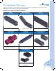
Kit Hardware Overview: If you can imagine it, you can build it with VEX IQ. Here’s an overview of common part types and their primary functions to help you get started. Common part types and primary functions Beams various sizes Specialty Beams angle, tee, right-angle beams Plates various sizes Structural parts. Structural parts. Structural parts. Connector Pins various lengths Standoffs various lengths Standoff Connectors various types Use with beams, plates, corner connectors, and more.
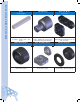
Mechanical Quick Start Guide Shaft various lengths Shaft Bushing Shaft Lock Plates various sizes Transmit power to, or allow rotation of, wheels, pulleys, gears, and more. Interfaces shafts with beams and plates, allowing the shaft to spin and be held in desired location. Plates that lock onto shafts allowing design components to spin with the shaft. Rubber Shaft Collars Twist Lock Shaft Collars Washers & Spacers Holds objects on shafts and/or the shaft itself in place.
Pulleys various sizes Rubber Belts various sizes Rubber Band Anchor Drive belts or make rollers and small wheels. Use with pulleys, as a form of stored energy, and/or as a fastener. Use with rubber belts and bands. Gears various sizes Wheel hubs and tires various sizes Smart Motor Transmit power to another gear and/or mechanism. Rolling and powering movement. Creates rotary motion.
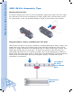
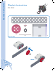
Mechanical Quick Start Guide VEX IQ Kit Assembly Tips: Removing Connector Pins To remove connector pins from structural components, gently push the pin with your finger from the back of the structural components to free it slightly, then it will be easier to pull it out. Alternatively, a shaft can be used instead of a finger to push the pin from the back. Fitting Small Gears, Pulleys, and Wheel Hubs onto Shaft VEX IQ shafts are built to last and run flawlessly in powered applications.
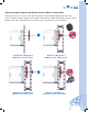
Keeping the Shaft Supported & Seated in Smart Motors & Assemblies Having a motor turn a shaft in the VEX IQ system is accomplished easily with only a few parts. However, without proper shaft support and either a rubber shaft collar and/or a shaft bushing, the shaft will quickly shift or fall out of your mechanism or Smart Motor.
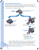
Mechanical Quick Start Guide Using VEX IQ Hardware: To get yourself acquainted with the VEX IQ system, build the Clawbot from the provided instructions on the following pages. The VEX IQ Clawbot was designed to be quickly and easily assembled, and then driven around using the included Driver Control program. The claw and storage “backpack” allow you to drive around, pick up, and store a variety of small objects.
C H A L L E N G E VEX IQ Challenge Once you’ve mastered building the Clawbot, challenge yourself further with the VEX IQ Challenge. Presented by the Robotics Education & Competition Foundation, the VEX IQ Challenge is a STEM program for elementary and middle school students (ages 8-14).
Clawbot Instructions Clawbot Instructions Part 1 Base 1x 4x 1x 1x Actual Size 1x 1x Step 1 10
1x 1x 2x 2x 4x 1x Actual Size Step 2 11
Clawbot Instructions 1x 1x 1x Actual Size 1x Step 3 12
1x 1x Actual Size 1x From Step 3 From Step 2 Step 4 13
Clawbot Instructions 1x 1x 1x Actual Size Step 5 F 1x Actual Size 1x Step 6 14
1x 1x Actual Size From Step 1 From Step 5 From Step 6 From Step 4 Step 7 15
Clawbot Instructions From Step 7 1x Step 8 Not Actual Size 16
1x 4x 1x 1x Actual Size 1x 1x Step 9 17
Clawbot Instructions 1x 1x 2x 2x 4x 1x Actual Size Step 10 18
1x 1x 1x Actual Size 1x Step 11 19
Clawbot Instructions 1x 1x Actual Size 1x From Step 11 From Step 10 Step 12 20
1x 1x 1x Actual Size Step 13 1x Actual Size 1x Step 14 21
Clawbot Instructions 1x 1x Actual Size From Step 9 From Step 13 From Step 12 From Step 14 Step 15 22
From Step 15 1x Not Actual Size Step 16 23
Clawbot Instructions 4x 2x 4x 2x 1x Actual Size Step 17 24
2x 8x 1x Actual Size Step 18 25
Clawbot Instructions 1 2 3 4 5 6 7 8 9 10 11 12 Actual Size 1x From Step 18 From Step 17 Step 19 26
Plug into Port 6 Plug into Port 1 Port 1 1 2 3 4 5 6 7 8 9 10 11 12 Port 6 Step 20 Refer to pages 85 through 111 for information on the built in Driver Control program in the Robot Brain. Robot Base is now Ready to Run! Test it before continuing the Build. • • • • • • Insert Robot Battery into Brain. Connect the Controller to the Robot Brain with the Tether Cable. Turn on the Robot Brain by pressing the check button. Run the Driver Control Program.
Clawbot Instructions Part 2 Claw 2x 1x 1x 1x 1x Use the 45° Angle Actual Size Step 21 1x 1x 1x Use the 30° Angle Actual Size 1x From Step 21 Step 22 28
1x Use the 45° Angle Actual Size From Step 22 Step 23 1x Use the 30° Angle Actual Size 1x From Step 23 Step 24 29
Clawbot Instructions Actual Size 1x Step 25 From Step 24 Actual Size 1x From Step 25 Step 26 30
2x 1x 1x 1x Use the 45° Angle Actual Size 1x Step 27 1x 1x 1x Use the 30° Angle Actual Size 1x From Step 27 Step 28 31
Clawbot Instructions 1x From Step 28 Use the 45° Angle Actual Size Step 29 1x Actual Size Use the 30° Angle 1x From Step 29 Step 30 32
Actual Size 1x Step 31 From Step 30 Actual Size 1x From Step 31 Step 32 33
Clawbot Instructions 2x Actual Size 1x Step 33 1x 1x Actual Size 2x Step 34 34
From Step 34 From Step 33 Step 35 Actual Size 1x From Step 35 Step 36 35
Clawbot Instructions 1x Actual Size Step 37 From Step 36 2x 2x Actual Size Step 38 36 Make (2x)
From Step 38 From Step 26 From Step 37 Step 39 Actual Size 1x From Step 39 Step 40 37
Clawbot Instructions From Step 32 Step 41 Actual Size From Step 41 38 1x Step 42
Actual Size 1x Leave Shorter for Motor Clearance 6x 2x Actual Size Step 43 39
Clawbot Instructions 1x Actual Size 4x 1x Actual Size Step 44 40
From Step 44 Step 45 From Step 43 41
Clawbot Instructions Part 3 Tower 1x 2x Actual Size 1x Step 46 4x Actual Size 1x Actual Size From Step 47 42 From Step 46 Step 47 Step 48
1x 2x 1x Actual Size Step 49 4x Actual Size 1x Actual Size From Step 49 Step 51 Step 50 From Step 50 43
Clawbot Instructions 1x Step 52 1x Actual Size 1x Actual Size 2x From Step 52 44 Step 53 2x
1x 1x Use the 60° Angle 2x Actual Size From Step 53 Step 54 45
Clawbot Instructions 1x Step 55 2x Actual Size Actual Size 1x 1x 2x From Step 55 Step 56 46
1x Actual Size 2x 2x Step 57 From Step 58 Step 58 From Step 48 47
Clawbot Instructions From Step 58 From Step 20 Step 59 48
From Step 50 Slide onto Shaft From Step 59 Step 60 Rotate to Vertical Step 61 Attach to Chassis 49
Clawbot Instructions 4x 1x Actual Size Step 62 From Step 61 From Step 62 Step 63 50
Step 64 Actual Size 1x From Step 56 Step 65 51
Clawbot Instructions Actual Size 1x From Step 65 Step 66 From Step 66 From Step 56 Step 67 52
4x 1x Actual Size Step 68 53
Clawbot Instructions From Step 68 Step 69 54
2x From Step 45 1x Use the 60° Angle Actual Size Step 70 1x Plug into Motor Plug Into Port 10 1 2 3 4 5 6 7 8 9 10 11 12 Not Actual Size Step 71 55
Clawbot Instructions 1x Plug Into Motor Step 72 Not Actual Size 56
Plug Into Port 11 Step 73 A 1 2 3 4 5 6 7 8 9 10 11 12 D B C E Raise Arm F POWER/LINK CHARGE/GAME R CHARGE TETHER L RADIO MODULE Open Claw Close Claw Lower Arm Robot Claw is now Ready to Run! 57
Clawbot Instructions Part 4 Ball Holder 4x Actual Size Step 74 58
Actual Size 2x Step 75 59
Clawbot Instructions 2x Actual Size Step 76 2x Actual Size Step 77 60
1x Actual Size 2x Step 78 1x 1x 2x Actual Size Step 79 61
Clawbot Instructions Actual Size 2x 1x Step 80 1x Actual Size 1x 1x Step 81 62
1x 2x Actual Size Step 82 Actual Size 2x 1x Step 83 63
Clawbot Instructions From Step 83 Step 84 Step 85 Step 86 64
Clawbot Instructions Part 5 Sensors Gyro 1x 4x Actual Size 1x Step 1 66
Step 2 From Step 1 67
Clawbot Instructions Touch LED 3x Actual Size 1x Step 1 68
1x Actual Size From Step 1 Step 2 69
Clawbot Instructions 1x From Step 2 Step 3 Connect Touch LED to any unused port on Robot Brain using a Smart Cable.
Distance Sensor 1x Actual Size 4x Step 1 71
Clawbot Instructions 1x Step 2 Connect Distance Sensor to any unused port on Robot Brain using a Smart Cable.
Bumper Switch 1x 4x Actual Size Step 1 1x Actual Size 4x From Step 1 Step 2 73
Clawbot Instructions 1x Actual Size Step 3 From Step 2 2x Actual Size Step 4 74
1x From Step 3 Connect Bumper Switch to Port 9 on Robot Brain using a Smart Cable.
Clawbot Instructions Color Sensor 1x 1x Actual Size Step 1 2x 1x Actual Size 76 Step 2 1x
1x Your Clawbot with Sensors is now ready to Run! Connect Color Sensor to any unused port on Robot Brain using a Smart Cable. Refer to pages 85-111 for important information about using your VEX IQ robot.
Autopilot Instructions Autopilot Instructions 2x 6x Actual Size From Step 20 on Page 27 Step 1 78
2x Actual Size Step 2 79
Autopilot Instructions 4x Actual Size Step 3 Connect Color Sensor to any unused port on Robot Brain with a Smart Cable 80 1x
4x Actual Size 1x Step 4 Connect Gyro Sensor to any unused port on Robot Brain with a Smart Cable 81
Autopilot Instructions 4x Actual Size Connect Touch LED to any unused port on Robot Brain with a Smart Cable 82 1x Step 5
1x Actual Size 4x Step 6 Connect Distance Sensor to any unused port on Robot Brain with a Smart Cable 83
Autopilot Instructions 8x 1x Actual Size Connect Bumper Switches to any unused ports on Robot Brain with a Smart Cable 84
Control System Overview Radio The VEX IQ Controller and Robot Brain communicate with each other through either wireless Radio Communication or Tether Cable. VEX Controller The VEX IQ Controller is at the center of what makes VEX IQ robots fun to build and easy to use. The controller allows you to drive your robot immediately through the use of two dual-axis analog joysticks and eight buttons. Robot Brain The VEX IQ Robot Brain is the powerful command center of your robot.
Control System Guide Robot Brain Setup Robot Battery Charging and Usage Items you need: • Robot Battery Charger P/N: 228-2743 • Battery Charger Power Cord appropriate for your region • Robot Battery P/N: 228-2604 See the Battery Safety information in the Appendices. Plug the Battery Charger Power Cord into Robot Battery Charger. Plug the power cord into an AC outlet. Insert the Robot Battery into the charger. The LED should turn red. The LED will turn green once the battery is charged.
Slide the Robot Battery into the Robot Brain until the latch clicks. To remove the Robot Battery, press the latch down and slide the battery out. Push Down on Latch l ul P Radio Installation and Removal Items you need: • Robot Brain P/N: 228-2540 • 900 MHz Radio P/N: 228-2621 The Robot Brain is designed to use a variety of Radio types, including the 900 MHz Radio. Be sure to use the same type of Radio in both the Robot Brain and the Controller.
Control System Guide Ensure there is no battery plugged into the Robot Brain. Slide the Radio into the Radio Socket. Orient the Radio so its VEX logo is away from the LCD screen. Press it in firmly. In the event the radio needs to be removed, the Robot Battery must be removed. Press the red button on the bottom of the Robot Brain while simultaneously pulling on the top of the Radio.
VEX Controller Setup Controller Battery Installation and Removal Items you will need: • Controller P/N: 228-2530 • Small Phillips head screwdriver • Controller Battery P/N: 228-2779 Notice: See the Appendices for Battery Safety and Disposal information Remove the battery door on the back of the Controller using a small Phillips head screwdriver. Gently install the Controller Battery, ensuring that the “+” and “-” contacts align with the power connector also marked “+” and “-”. Reinstall battery door.
The VEX Controller Battery can only be charged while installed in the Controller. See the Battery Safety information in the Appendices. There are two ways to charge the Controller Battery: Option A: Turn off the Controller. Connect the Controller to a USB port on a PC or a USB Wall Adaptor using the USB Cable P/N: 228-2785. Charging will start automatically. This is the recommended charging method.
Controller Battery charging will take about 4 hours. While the Controller Battery is charging, the Charge/Game LED on the Controller will be solid red. When the Controller Battery is fully charged, the LED will change to solid green. See page 95 for detailed LED color diagram.
Control System Guide Removing the Radio should rarely, if ever, be done. To remove the Radio, first remove the battery door using a Phillips head screwdriver. Pull firmly on the Radio to remove it. Initial Wireless Setup Items you will need: • Robot Brain with Radio and Robot Battery installed • VEX Controller with Radio and Controller Battery installed • Tether Cable P/N: 228-2786 In order for the Robot Brain and Controller to communicate wirelessly, they must be paired together.
Turn the Robot Brain ON by pressing the Check button. The Controller will automatically link and pair to the Robot Brain. The Tether Icon will appear on the Robot Brain LCD screen. Programs Driver Control Autopilot Select Settings Tether Icon. See table below for explanation. Remove the Tether cable from Robot Brain and Controller. They are now communicating wirelessly as indicated by the Radio Bar icon on the LCD screen.
Control System Guide Power On and OFF Robot Brain ON: Press the Check button. VEX Controller ON: Press the Power button. 1 2 3 4 5 6 Check Button A D B C E F POWER/LINK CHARGE/GAME “X” Button Power Button 7 8 9 10 11 12 Power OFF Turning off the VEX Controller or Robot Brain will automatically turn OFF the other unit, if the units are connected wirelessly. VEX Controller OFF: press and hold the Power Button for 2 seconds. Robot Brain OFF: press and hold the “X” Button for 2 seconds.
VEX Controller The color of the LEDs indicates the status of the Controller. Review table below. This information is very helpful when working with the Controller.
Control System Guide Driver Control Program The Driver Control Program is a default program built into the Robot Brain so it can be used with the Controller without programming. It maps the Controller joysticks and buttons to control specific ports on the Robot Brain. There are three modes in the Driver Control Program: Left Stick, Right Stick, and 2 Joystick.
In both Left Stick and Right Stick mode, one joystick will be used to drive the robot. In Right Stick the D axis on the right joystick will be used to drive the robot forward and backward. The C axis will be used to turn the robot left and right. In Left Stick, the A axis on the left joystick will be used to drive the robot forward and backward. The B axis will be used to turn the robot left and right.
Control System Guide Random Mode Spiral Mode Lawnmower Mode The robot will randomly explore your room by driving in a straight line. When it encounters obstacles, it will backup, spin a random amount, and depart in a new direction. The robot will begin to explore by driving in a spiral with an ever increasing radius. When it encounters an obstacle, the robot will drive to a new location and begin to spiral again.
The default explore mode is Random Mode. To change between the three different modes, a Touch LED and or Color Sensor must also be connected to the Robot Brain. Tapping the Touch LED will cycle through the available explore modes. The current explore mode will be shown by illuminating the Touch LED in red for Random Mode, blue for Spiral Mode, and green for Lawnmower Mode.
Control System Guide Start Screen and List of Programs Programs The Programs Screen of the Robot Brain is the first screen displayed after turning on the Robot Brain, and will contain a list of all programs that have been downloaded to it. The default program is Driver Control, which allows you to use and control up to eight Smart Motors and four Sensors. If additional programs have been downloaded to the Robot Brain, use the Up/Down arrows to navigate between programs.
Program Running Screen Programs › Driver Control › Run The Driver Control program is now running on the Robot Brain; the table on Page 96 contains the default mapping between the buttons on the Controller and the Smart Ports on the Robot Brain. While a program is running, a clock will be displayed showing the total time that the program has been running. To stop the program, press the Check button. After stopping the program the Check Button will run it again. To exit the program, press the X button.
Control System Guide Configure Drive Control Programs › Driver Control › Configure To customize the Driver Control program, exit any currently running programs and select Configure from the Home Screen › Driver Control menu. Configure Control Drive Motor 4 Motor 5 Motor 10 Enter 2 Normal Normal Normal Normal Exit Use Up/Down arrows to highlight Configure, then press the Check button.
Settings The Settings screen is accessed by pressing the X button while on the Programs. This menu contains system wide options and information about the Robot Brain and VEX IQ Controller. The first row will either contain the text Sound On or Sound Off, depending on which option is currently set. To change this setting, press the Check button while this row is selected.
Download Port (Robot Brain) The Download port is used to program the Robot Brain using either Modkit for VEX or ROBOTC. The Download port can also be used to upgrade the firmware in the Robot Brain. See vexrobotics.com/vexiq/firmware to get the VEX IQ Firmware Utility. Download Port DOWNLOAD TETHER Charge Port (VEX Controller) The Charge port is only used to charge the Controller. See page 90 for charging instructions.
Tether Port (VEX Controller and Robot Brain) The Tether Port has three functions: R DOWNLOAD CHARGE TETHER L TETHER RADIO MODULE Tether Port Tether Port 1. It is used to “Pair” the Robot Brain with a Controller. Pairing is required to make the Robot Brain and Controller communicate with each other. Once paired, the process does not need to be repeated, unless you want a different Controller to communicate with the Robot Brain. See Page 92 for more information about the Wireless Setup. 2.
Control System Guide Connecting a Smart Motor Items you will need: • • • • Robot Brain with Radio and Robot Battery installed VEX Controller with Radio and Controller Battery installed Smart Motor P/N: 228-2560 Smart Cable P/N: 228-2780 Smart Motors are used to make your robotic creations come alive with motion. The Smart Motors are connected to the Robot Brain using Smart Cables. These cables come in assorted lengths between 200mm and 600mm long.
Connecting a Bumper Switch Items you will need: • • • • • Robot Brain with Radio and Robot Battery installed VEX IQ Controller with Radio and Controller Battery installed Smart Motor P/N: 228-2560 Bumper Switch P/N: 228-2677 Smart cable P/N: 228-2780 Bumper switches are input devices that give the Robot Brain a signal when they are pressed. Bumper Switches can be used to turn off a motor when pressed. All VEX IQ electronics are connected to the Robot Brain using Smart Cables.
Control System Guide Connecting a Touch LED Items you will need: • Fully assembled VEX IQ Robot such as the Standard Drive Base, Autopilot Robot, Clawbot or Clawbot with Sensors (See Page 8 for more information), Radio, and Robot Battery installed in the Robot Brain • VEX IQ Controller with Radio and Controller Battery Installed • Touch LED (228-3010) The Touch LED is an input device that responds to interaction from a person touching the top dome.
Connecting a Distance Sensor Items you will need: • Fully assembled VEX IQ Robot such as the Standard Drive Base, Autopilot Robot, Clawbot or Clawbot with Sensors (See Page 8 for more information), Radio, and Robot Battery installed in the Robot Brain • VEX IQ Controller with Radio and Controller Battery Installed • Distance Sensor (228-3011) The Distance Sensor is an input device that measures the distance to an object by using high frequency sound waves.
Control System Guide Connecting a Color Sensor Items you will need: • Fully assembled VEX IQ Robot such as the Standard Drive Base, Autopilot Robot, Clawbot or Clawbot with Sensors (See Page 8 for more information), Radio, and Robot Battery installed in the Robot Brain • VEX IQ Controller with Radio and Controller Battery Installed • Color Sensor (228-3012) The Color Sensor is an input device that senses the color of an object. Color Sensors are connected to the Robot Brain using Smart Cables.
Connecting a Gyro Sensor Items you will need: • Fully assembled VEX IQ Robot such as the Standard Drive Base, Autopilot Robot, Clawbot or Clawbot with Sensors (See Page 8 for more information), Radio, and Robot Battery installed in the Robot Brain • VEX IQ Controller with Radio and Controller Battery Installed • Gyro Sensor (228-3014) The Gyro Sensor is a device that can detect how quickly an object is rotating. Gyro Sensors are connected to the Robot Brain using Smart Cables.
Appendix A Battery Safety and Disposal Appendix A Battery Safety and Disposal 228-2779 VEX IQ Controller Battery Rules • Avoid letting children play with the battery. • Dispose of the battery properly. • Do not use, leave, store or charge the battery close to any heat source or at very high temperatures (for example, in strong direct sunlight or in a vehicle in extremely hot weather). • Do not heat or set the battery on fire. • Do not puncture, cut, beat, throw, drop or chisel the battery.
228-2743 Robot Battery Charger CAUTION! Adults are recommended to periodically examine the transformer and power cable for conditions that may result in the risk of fire, electric shock, or injury (such as damage to the output cord, plug, housing or other parts) and in the event of such conditions, the transformer should not be used until properly repaired or replaced. The transformer is for indoor use only.
Appendix B Compliance Statements Appendix B Compliance Statements FCC Compliance Statement (United States) This device complies with part 15 of the FCC Rules. Operation is subject to the following two conditions: 1. This device may not cause harmful interference, and 2. This device must accept any interference received, including interference that may cause undesired operation.
Industry Canada Compliance Statement Industry Canada Compliance Statement (except 228-2621) This Class B digital apparatus complies with Canadian ICES-003. Cet appareil numérique de la classe B est confirme à la norme NMB-003 du Canada. Industry Canada Compliance Statement (228-2621) Compliance with Industry Canada standards This device complies with Industry Canada licence-exempt RSS standards(s).
Super Kit Inventory Super Kit Inventory VEX IQ Super Kit 116 1x4 Beam (10x) 1x6 Beam (10x) 1x8 Beam (12x) 1x12 Beam (6x) 2x2 Beam (8x) 2x4 Beam (8x) 2x6 Beam (8x) 2x8 Beam (8x) 2x12 Beam (6x) 2x16 Beam (6x) 4x4 Plate (4x) 4x12 Plate (2x) 1x1 Connector Pin (240x) 1x2 Connector Pin (60x) 2x2 Connector Pin (20x) 1/2x Pitch Standoff (6x) 1x Pitch Standoff (6x) 2x Pitch Standoff (12x) 4x Pitch Standoff (10x) 6x Pitch Standoff (10x) Shaft Washer (40x) 1/4x Pitch Shaft Spacer (50x) 2x Pitc
Small Chassis Corner Connector (30x) 2x Wide, 1x2 Corner Connector (10x) 1x Wide, 1x1 Offset Corner Connector (20x) 2x Wide, 2x1 Offset Corner Connector (8x) 2x Wide, 2x1 Corner Connector (6x) 2x Wide, 1x1 Offset Corner Connector (6x) 2x Wide, 2x2 Corner Connector (10x) 2x Wide, 1x2 Offset Corner Connector (8x) 2x2 Shaft Lock Plate (2x) 1x3 Shaft Lock Plate (4x) Rubber Shaft Collar (40x) 3x4 Tee Beam (4x) 2x3 Right Angle Beam (4x) 30 Degree Angle Beam (4x) 45 Degree Angle Beam (4x) 60 Degree
Super Kit Inventory 12 Tooth Gear (10x) 36 Tooth Gear (10x) 60 Tooth Gear (6x) 36 Tooth Crown Gear (4x) 30mm Rubber Belt (2x) 40mm Rubber Belt (2x) 50mm Rubber Belt (2x) 60mm Rubber Belt (2x) Inner Twist Lock Shaft Collar (4x) Outer Twist Lock Shaft Collar (4x) Controller (1x) Robot Brain (1x) Smart Motor (4x) Robot Battery (1x) 900 MHz Radio (2x) VEX Controller Battery (1x) 200mm Smart Cable (4x) 300mm Smart Cable (4x) 400mm Smart Cable (2x) 600mm Smart Cable (2x) Bumper Switch (2x) R
Expand and conquer. Once you’ve mastered the CLAWBOT, we challenge you to move onto even more advanced robot designs. Of course, all VEX mechanical gears, wheels, hardware and structural parts are cross-compatible for endless design possibilities. With hundreds more upgrade parts and accessories, the creative possibilities for your robot designs are limitless. Visit www.VEXROBOTICS.com/VEXIQ for more information.