
Instructions / Assembly
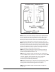

STEP 3. Locate the full-size mounting template at the desired location
with the top hole at the top position and tape in place. Drill the three
each 11/32" diameter holes perpendicular to the face of the dash.
Then cut or drill the 3" diameter center hole. Locate the Mounting
Bracket (#1 or #8) on the dash and secure with the Bolts (#2), Washers
(#3) and Lock Nuts (#4) supplied. Torque the Lock Nuts to 50 in. lbs.
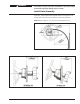
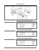
STEP 4. The Helm Assembly can be rotated on the Mounting Bracket to
accommodate Cable entry. The best position for the Drive Unit is where
the Cable can be installed with the minimum amount of bending. Figure
4 shows the Cable End positions for either PUSH or PULL for right turn
operation. The Drive Assembly is adjustable in 45 degree increments
from the top right or top left cable entry positions.
Figure 4.
STEP 5. Insert the Helm through the cutout in the dash. Attach the
Helm to the Mounting Bracket (#1 or #8) and secure with Bolts (#5)
provided. Torque the Bolts to 25-30 in. lbs.
STEP 6. For 20° Bezel Kit—Place Trim Bezel (#9) over the Shaft with
the word “Vevor” pointing upwards, and secure with screws (#16). STEP
7. For 90° Bezel Kit—Place Trim Bezel (#7) over the Shaft with
the word “Vevor” pointing upwards, and snap in place over
the three lugs on the Mounting Bracket (#1).
STEP 8. Place the Key (#6) into the slot on the Steering Shaft as shown
in the Parts Breakdown. Align the Key (#6) with the keyway in the
steering wheel and slide the steering wheel onto the Shaft.
STEP 9. Install the Washer (#10) and the Nut (#11) and tighten to
25-30 in. lbs.
Page 4 of 6