Table Of Contents ABOUT THIS MANUAL .. | Scope 1 SAFETY INSTRUCTIONS. INTRODUCTION Basic System Architectures 2 PRODUCE OBLIVION. eee nse oss messes ro 3 INSTALLATION .. Preparation Mounting the Unit Battery Connection... se AC Outputting Connection 7 PV Connection Final Assembly 9 COMMUNICATION . . SO Dry Contact Signal 10 Power ONION Operation and Display Panel LCD Display Icons LCD Setting Display Sting nt Operating Soda Description Fault Reappearance Code. Warning Indicator SPECIFICATIONS ..
ABOUT THIS MANUAL Purpose This manual describes the assembly, Installation, operation and troubleshooting of this unit, Please read this manual carefully before installations and operations. Keep this manual for future reference. Scope “This manual provides safety and Installation guidelines as well as Information on tools and wiring. SAFETY INSTRUCTIONS WARNING: This chapter contains Important safety and operating Instructions. Read and keep this manual for future reference. 1.
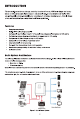
INTRODUCTION ‘This is a multi-function inverter/charger, combining functions of inverter; MP PT solar charger and battery charger to offer uninterruptible power support with portable size, Tis comprehensive LCD display offers user-configurable and easy-accessible button operation such as battery charging current, AG/solar charger priority, and acceptable Input voltage based on different applications.
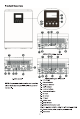
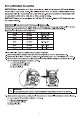
AKIVA! SKA single model 9 EF © 1-3KVA mode! NOTE: For parallel mode! installation and operation, please check separate parallel Installation guide for the details. AKVA/SKVA parallel model . LD display . Status Indicator . Charging Indicator Fault indicator . Function buttons . Power offing switch . AC Input . AC output . PV Input 10. Battery input 11. Cultural breaker 12. RS232 communication port 13. Parallel communication cabin (only for parallel model} 14.
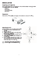
INSTALLATION Unpacking and Inspection Before Installation, please Inspect the unit. Be sure that nothing Inside the package Is damaged. You should have received the following items inside of package: * The unit 1 * User manual x 1 + Communication cable x 1 » Software CDx 1 Preparation Before connecting all wiring, please take off bottom cover by removing two screws as shown below.
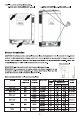
Install the unit by screwing three screws. 1-3KVA 24V, 1KVA/3KVA 48V model 2-IKVA 24V/48V Plus, 4-5KVA 48V model Battery Connection CAUTION: For safety operation and regulation compliance, Its requested to Install a separate DC over-current protector or disconnect device between battery and inverter. It may not be requested to have a disconnect device In some applications, however, It's still requested to have over current protection Installed. Please refer cal in bel I i ize.
Please follow below steps to Implement battery connection: 1. Assemble battery ring terminal based on recommended battery cable and terminal size. 2. Connect all battery packs as units requires. IV's suggested to connect at least 100th capacity battery for 1-3KVA model and at least 200th capacity battery for 4KVA/SKVA model. NOTE: Please only use sealed lead acid battery or sealed MAGELLAN lead-acid battery. 3.
AC Input/Output Connection CAUTION II Before connecting to AC Input power source, please Install a separate AC breaker between inverter and AC input power source. This will ensure the inverter can be securely disconnected during maintenance and fully protected from over current of AC Input. The recommended spec of AC breaker Is 104 for AKIVA, 20A for AKIVA, 32A for AKIVA, 404 for AKIVA and 50A for SKA. CAUTION There are two terminal blocks with “IN” and “OUT” markings.
5. Make sure the wires are securely connected. CAUTION: Important Be sure to connect AC wires with correct polarity. If L and N wires are connected reversely, It may cause utility short-circuited when these inverters are worried in parallel operation. CAUTION: Appliances such as air conditioner are required at least 2~3 minutes to restart because it's required to have enough time to balance refrigerant gas Inside of cults.
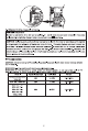
PV Moguls Selection: When selecting proper PY modules, please be sure to consider below parameters: 1. Open circuit Voltage (Voc) of PV modules not exceeds max. PY array open circuit voltage of inverter. ultra Voltage (Voc) of PY modules should be higher than min. battery voltage. Solar Charging Mods. uA [| vulvae AKIVA 48V INVERTER MODEL IKVAZAV | ey | Pius/ AKIVA | Plushness 48V AKIVA 24 Pius 4KVA/SKVA Max.
Communication Connection Please use supplied communication cable to connect to Inverter and PC. Insert bundled CD Into a computer and follow on-screen Instruction to Install the monitoring software. For the detailed software operation, please check user manual of software Inside of CD. Dry Contact Signal There is one dry contact (3A/250VAC) available on the rear panel. It could be used to deliver signal to external device when battery voltage reaches warning level. Unit Status.
OPERATION Power ON/OFF Once the unit has been properly Installed and the batteries are connected well, Imply press On/Off switch (located on the button of the case) to tum on the unit. Operation and Display Panel ‘The operation and display pane, shown In below chart, Is on the front panel of the Inverter, It Includes three indicators, four function keys and a LCD display, indicating the operating status and input/output power Information.
LCD Display Icons Re Mimi EERIE Icon Input Source Information Indicates the AC Input. Indicates the PV input wear . i Indicate input voltage, input frequency, PV voltage, battery voltage and BEE | camera: Configuration Program and Fault Information H a Indicates the setting programs. © Indicates the waning and fault codes.
In battery mode, it will present battery capacity. Load Percentage Battery Voltage Load >50% ~ 1.8 ~ > 1.883 V/cell 50%> Load > 20% < ~ 1.9 ~ > 1983 Load < 20% < ~ 1.95 ~ >2033 Indicates overload. Indicates the load level by 0-24%, 25-50%, 50-74% and 75-100%. J / SEE / Mode Operation Information & Indicates unl connects to the mains. Fo Indicates unit connects to the PV panel. Indicates load Is supplied by utility power. Indicates the utility charger ultra Is working.
LCD Setting After pressing and holding ENTER button for 3 seconds, the unit will enter setting mode. Press “UP” or "DOWN" button to select setting programs. And then, press “ENTER” button to confirm the selection or ESC button to ait. Setting Programs: Program Description Ineluctable option Escape 00 Exit setting mode rey Ps ug £50 Solar energy provides power to the loads as first priority.
104 (Not available for 2-3KVA 24 Plus) za oe ome Hg cls Fd 308 408 504 60A (default) son 708 BoA S0A 100A |0a00110A 120A Zuo: |02ien308 T40A orient 02 Ho ‘Appliances (default) | If selected, acceptable AC input fn 5. | voltage range will be within 0 | cpt voltage mn 03 BRL 90-280VAC. ve [ IF selected, acceptable AC Input Mn i voltage range will be within 03 LPS 170-280VAC.
12 Setting voltage point back to utility source when selecting "SBU priority” or “Solar first” In program 01. Available options in 24V models: i? Zen ig 28g 23.0V (default) 23.
13 Setting voltage point back to battery mode when selecting "SBU priority” or "Solar first” In program 01. 25.5v 3 2s 26.
If this Supercharger ks working In Line, Standby or Fault mode, charger source can be programmed as below: Solar first Bb CSO Solar energy will charge battery as first priority. Utility will charge battery only when solar energy Is not available. Utility first Utility will charge battery as first { 11 priority. 1 b LUE Solar energy will charge battery only Charger source priority: wham utility power Is not available. 16 | To configure charger source | Solar and Utility priority (Only available for | o\ ener
Record Fault code Record enable Record disable {default} 25 FEN 25 FdS Bulk charging voltage (CV voltage) 24v model default setting: 28.2 chary 48V mode! default setting: 56.4V fv 26 shy If self-defined ls selected In program 5, this program can be set up. Setting range is from 24.0V to 29.2V for 24V model and 48.0V to 58.4V for 48V model. Increment of each click Is 0.1v. 7 Floating charging voltage 24v mode default to 27.0V Fo 2) Sp 48V mode! default setting: 54.
Solar power balance | if selected, the solar input power disable: will be the same to max. battery charging power no matter how much loads are connected. The max. battery charging power will @ d be based on the setting current In program 02. {Max solar power = Max. battery charging power Display Setting The LCD display Information will be switched In turns by pressing “UP” or “DOWN” key.
MP PT Charging power MP PT charging PowerPoint ig suit =500" 230 Battery voltage/ DC discharging current Output frequency =50Hz Lae Output frequency Load percentage When connected load Is lower than Akiva, load In VA will present Jo Ova like below chart. Load in VA When load Is larger than Akiva { 1KVA), road In VA will present drawing like below chart.
When oad ks lower than 1kW, load In W will present o0W like below chart. wey =o Load in Watt When load Is larger than 1kW ( 1KW), oad In W wil present dW lke below chart.
Operating Mode Description Operation mode Description LCD display Standby made / Power saving mode Nita: “Standby mode: The verier Is not muted on yet but at this time, the Inverter can charge battery without AC output. “Power saving mode: IF ‘enabled, the output of inverter Wil be off when connected load Is pretty low or not detected, No output is supplied by the unit bus It stl can charge: batteries. Charging by utility. Charging by PY energy. No charging. = Charging by utility.
QA, jj Power from battery and PV energy. AE sof [oles The unit will provide output 2 i. or Battery Mode power from battery and PV hd power Power from battery only. Fault Reference Code Fault Code Fault Event 0 Fan Is locked when Inverter ks off. 2 Over temperature 03 Battery voltage Is too high 04 Battery voltage Is too low = ‘Output short circulated or over temperature is detected w by Internal converter components. Pau % Output vortex f abnormal. (For LG2K73K model) | Tir Output vantage Is too high.
Warning Indicator Weening Warning Event Audible Alarm Icon flashing on Fan is locked when Beep three times every Inverter s on. second a Battery ks over-charged | Beep once every second 4 Low battery Beep once every second 7 Overload Beep once every 0.5 second 10 Output power aerating | Beep twice every 3 seconds 2 Solar charger stops due to low battery. IN Solar charger stops due to high PV voltage. » Solar charger stops due to overload.
SPECIFICATIONS Table 1 Line Mode Specifications When AC input voltage drops to 55 or 170V depending on models, the output power will be aerated.
TROUBLE SHOOTING Problem LCD/LED/Buzzer | Explanation { Possible cause What to do Unf shuts down | DOGSLEDS and buzzer automatically wil benefactor | The battery voltage is ton low | 1. Re-charge battery. during startup seconds and then | 2. Replace battery. process. complete off. 1. The battery voltage ks far too | 1. Chick I batteries and the No response Ber | vo cation low. wiring are connected wel. power on. " 2. Battery polarity Is connected 2. Re-charge battery. reversed. 3. Replace battery.
Appendix: Approximate Back-up Time Table Model Load (VA) | Backup Time @24Vdc 1004th (min) | Backup Time @24Vdc 200th (min) 200 766 1610 400 335 766 AKIVA 600 198 503 800 139 339 1000 112 269 200 766 1610 400 335 766 600 198 503 800 139 339 1000 112 269 A 1200 95 27 1400 81 176 1600 62 140 1800 55 125 2000 50 112 300 449 1100 600 222 525 900 124 303 1200 95 27 1500 8 164 wa 1800 56 126 2100 4 108 2400 35 9 2700 31 74 3000 2 67 Model Load (VA) | Backup Time @ 48Vdc 100th (min) | Backup Time @ 48Vdc 200th (mi
Model Load (VA) | Backup Time @ 48Vdc 100A (min) | Backup Time @ 48Vdc 200th (min) 200 1581 3161 400 751 1501 600 1 1054 800 331 760 1000 268 615 2A 1200 221 508 1400 7 387 1600 136 335 1800 120 295 2000 106 257 300 1054 2107 600 491 1054 500 291 668 1200 196 497 1500 159 402 Ha 1800 123 301 2100 105 253 2400 91 219 2700 7 174 3000 63 155 400 766 1610 800 335 766 1200 198 503 1600 139 33 2000 112 269 KA 2400 95 27 2800 81 176 3200 62 140 3600 55 125 4000 50 112 500 613 1269 1000 268 613 1500 158 402 2000 11