
Use and Care Manual


40
5
5
5
5
4
6
4
6
2
1
3
8
9
7
OPERATING INSTRUCTIONS
Laser Adjustment
DANGER
Laser radiation. Avoid direct eye contact with light source.
WARNING
Use of controls or adjustments or performance of procedures
other than those specified herein could result in hazardous
radiation exposure.
When the laser guides switch is turned on, it will generate
a red line. The laser line is pre-adjusted at the factory and
the laser line should be aligned with the cutting wheel.
If the laser line isn’t aligned with cutting wheel, make
adjustment as below:
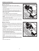
• Turn wheel guard lock knob counterclockwise to unlock.
Pull wheel guard open.
• Turn the laser on .
• Loosen two screws and remove the laser box cover.
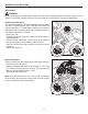
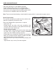
To adjust the laser angle:
• Loosen the lock screw a 1/4 of a turn with 2 mm
hex wrench (not supplied) so the laser can beadjusted.
Note: Do not remove the lock screw.
• Adjust the adjustment screw clockwise or counterclockwise
until the laser line is aligned with cutting wheel.
• Once aligned, tighten the lock screw.
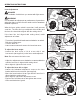
To adjust the laser left or right:
• Loosen the horizontal adjustment screw on the laser
bracket with 3mm hex wrench (not supplied).
• Move the laser bracket left or right until the laser line is
aligned with the cutting wheel.
• Once aligned, tighten the adjustment screw.
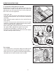
• Replace the laser box cover and tighten two screws.
• Close and lock wheel guard.
Laser box
cover
Laser box
cover
ScrewScrew
Adjustment
screw
Horizontal
adjustment
screw
Lock screw
Adjustment
screw
Horizontal
adjustment
screw
Lock screw