Technical Support and E-Warranty Certificate www.vevor.com/support WET TILE SAW MODEL:TC250VI-I We continue to be committed to provide you tools with competitive price. "Save Half", "Half Price" or any other similar expressions used by us only represents an estimate of savings you might benefit from buying certain tools with us compared to the major top brands and doses not necessarily mean to cover all categories of tools offered by us.
WET TILE SAW MODEL:TC250VI-I NEED HELP? CONTACT US! Have product questions? Need technical support? Please feel free to contact us: CustomerService@vevor.com This is the original instruction, please read all manual instructions carefully before operating. VEVOR reserves a clear interpretation of our user manual. The appearance of the product shall be subject to the product you received. Please forgive us that we won't inform you again if there are any technology or software updates on our product.
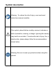
Symbol description Warning - To reduce the risk of injury, user must read instructions manual carefully. This symbol, placed before a safety comment, indicates a kind of precaution, warning, or danger. Ignoring this warning may lead to an accident. To reduce the risk of injury, fire, or electrocution, please always follow the recommendation shown below. Warning- Be sure to wear eye protectors when using this product.
TABLE OF CONTENTS Product Specifications......................................................................................................... 2 Package Contents ............................................................................................................... 3 Hardware Contents ..............................................................................................................4 Safety Information ....................................................................................
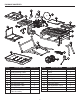
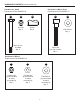
PACKAGE CONTENTS C A D F B E G H T R I S J Q L K P O N PART A B C D E F G H I J DESCRIPTION Rear Extension Tray-1 Rear Extension Table Rear Rubber Flap Side Rubber Flap Motor Head Assembly Cutting Wheel Side Extension Tray Side Extension Table Sliding Table Frame and Sliding Table Assembly QUANTITY 1 1 1 1 1 1 1 1 1 1 PART K L M N O P Q R S T 3 DESCRIPTION Sliding Table Lock Knob Handle Pump Wheel Miter Guide Water Tray Stand Assembly Rear Extension Tray-2 Arbor Wrench Hex Wrench M QUA
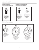
HARDWARE CONTENTS (shown actual size) Hardware for Stand Replacement Part #108505116 CC Hardware for Motor Head Replacement Part #108505117 DD EE Hex Nut Qty. 4 Spacer Qty. 8 FF Flat Washer Qty. 4 M8 x 85 mm Hex Bolt Qty. 4 M10 x 60 Hex Cap Screws Qty. 4 Hardware for Wheel Replacement Part #108505118 HH Locking Nut (preassembled to stand assembly Q) Qty. 2 GG II JJ Flat Washer (preassembled to stand assembly Q) Qty. 2 Flat Washer (preassembled to stand assembly Q) Qty.
HARDWARE CONTENTS (shown actual size) Hardware for Handle Replacement Part #108505119 Hardware for Rear Rubber Flap Replacement Part #108505120 LL M8 x 16 mm Hex Bolt (preassembled to handle L) Qty. 2 MM NN M5 x 12 mm Cross Screw (preassembled to motor head assembly E) Qty. 1 Big Flat Washer (preassembled to motor head assembly E) Qty. 1 Blade Locking Assembly Replacement Part #108505121 OO PP QQ Inner Washer (preassembled to tile saw CC) Qty. 1 Outer Washer (preassembled to tile saw CC) Qty.
SAFETY INFORMATION Please read and understand this entire manual before attempting to assemble, operate, or install the product. This manual contains information that relates to PROTECTING PERSONAL SAFETY and PREVENTING EQUIPMENT PROBLEMS. It is very important to read this manual carefully and understand it thoroughly before using the product. The symbols listed below are used to indicate this information. DANGER Potential hazard that will result in serious injury or loss of life.
SAFETY INFORMATION OPERATION/WORKPLACE • KEEP GUARDS IN PLACE and in working order. • REMOVE ADJUSTING KEYS AND WRENCHES. Form habit of checking to see that keys and adjusting wrenches are removed from tool before turning it on. • KEEP CHILDREN AWAY. All visitors should be kept at a safe distance from work area. • MAKE WORKSHOP CHILDPROOF with padlocks, master switches or by removing starter keys. • DO NOT FORCE TOOL. It will do the job better and safer at the rate for which it was designed.
SAFETY INFORMATION • MAINTAIN TOOLS WITH CARE. Keep tools sharp and clean for best and safest performance. • Follow instructions for lubricating and changing accessories. • A cutting disc can cause injuries, even when stationary! Use protective gloves to change the cutting disc. • NEVER use lateral counter pressure to bring the cutting disc to a standstill after switching off the drive. • Replace table insert when worn. • Use only diamond discs recommended by the manufacturer.
SAFETY INFORMATION WARNING The tool is loud and the sound can cause hearing damage. ALWAYS wear ear protection to help prevent hearing damage and loss. Failure to comply may result in moderate injury. READ OPERATOR’S MANUAL To reduce the risk of injury, user must read and understand operator’s manual before using this product. • USE SAFETY GOGGLES AND EAR PROTECTION • ALWAYS WEAR EYE PROTECTION THAT CONFORMS WITH UL REQUIREMENTS. FLYING DEBRIS can cause permanent eye damage.
SAFETY INFORMATION ELECTRICAL SAFETY CAUTION In all cases, verify that the outlet in question is properly grounded. If you are not sure, have a licensed electrician check the outlet. GROUNDING INSTRUCTIONS In the event of a malfunction or breakdown, grounding provides a path of least resistance for electric current to reduce the risk of electric shock. This tool is equipped with an electric cord that has an equipment-grounding conductor and a grounding plug.
SAFETY INFORMATION PREPARATION Before beginning assembly of product, make sure all parts are present. Compare parts with package contents list and hardware contents list. If any part is missing or damaged, do not attempt to assemble the product. Tools Required for Assembly (not included): 13 mm open wrench, adjustable wrench. ASSEMBLY INSTRUCTIONS UNPACKING This product requires assembly. • Carefully lift the saw from the carton and place on a level work surface.
ASSEMBLY INSTRUCTIONS Installing Stand Assembly to Frame and Sliding Table Assembly 1. Turn the sliding table lock knob (K) counter-clockwise to horizontal position to lock the sliding table (I). Place the frame and sliding table assembly (J) upside down on the protective material. 1 I Note: Place cardboard or an old blanket as protective material on floor in order to protect the surface of the sliding table. K J 2.
ASSEMBLY INSTRUCTIONS 3. Remove lock nut (HH) and flat washer (II) preassembled to stand assembly (Q) from each axle. 3 JJ Note: Leave one flat washer (JJ) on each axle. 2 II II Q 2 HH JJ 1 4. Slide wheel (N) and flat washer (II) (removed in previous step) onto axle of stand assembly (Q). Secure with lock nut (HH) (remove in previous step). Repeat for remaining wheel. 4 Note: Kobalt logo on wheel should face outside of stand.
ASSEMBLY INSTRUCTIONS 5. Remove lock nut (UU) preassembled to handle (L) from handle (L). 5 2 2 1 6. Attach handles (L) to Frame. Secure with lock nut (UU) (removed in previous step).
ASSEMBLY INSTRUCTIONS 7. Grasp the handles and tilt stand, frame and sliding table assembly back onto wheels until the stand is balanced on the wheels and stand support assembly. 7 8. Step on the release lever and pull the handles toward you at the same time. Once the stand is released from the release lever, ease the stand toward the floor by pushing the handles toward the floor.
ASSEMBLY INSTRUCTIONS 9. With your hands on the handles, push the stand toward the ground until the stand is in an open position. 9 2 2 1 Installing Motorhead to Sliding Table, Frame and Stand Assembly 1 E 1. Align holes in motor head assembly (E) with holes on side of metal frame. Insert hex cap screw (FF) through flat washer (GG) into motor head assembly and side of frame. Secure with hex wrench.
17
ASSEMBLY INSTRUCTIONS Installing the Rear Extension Table 1 1. Align the tabs on the rear extension table (B) with matching holes on the sliding table (I) and push the tabs into holes. Push down the rear extension table to horizontal position and at the same time pull the lock pin underside of the rear extension table) toward to sliding table. Release the lock pin to lock place. B 1 1 2 I 3 Lock pin Lock pin 2 1 Installing the Side Extension Table H 1 1.
ASSEMBLY INSTRUCTIONS Installing the Water Tray and Tray Extensions 1 R 1. Take side extension tray (G) and two rear extension tray (A, R) out of water tray (P). G A P 2. From left side of the saw, push water tray (P) into frame and stand assembly. 2 P 3. Standing at back of saw, push rear extension tray-1 (A) into frame and secure it onto the two holders mounted on the frame assembly.
20
1 2 21
ASSEMBLY INSTRUCTIONS 2. Pull the plug for pump out from the opening molded in the water tray. Push back rubber boot on the electrical cord and plug water pump into receptacle. Pull boot cover cord connections to help keep water off plug. Any excess cord can be wrapped on the two hooks. 2 Note: The receptacle is only connected with the water pump. Note: The pump could also be used on a separate bucket.
ASSEMBLY INSTRUCTIONS Tile Cutting Wheel For maximum performance and safety, it is recommended that you use the 10 in. cutting wheel provided with your saw. Additional cutting wheels are available at your local retailer. WARNING DO NOT use cutting wheels rated less than the no load speed of this tool. Failure to heed this warning could result in personal injury. DO NOT use a wheel with cracks, gaps, or teeth. Installing the Tile Cutting Wheel WARNING • A 10 in.
ASSEMBLY INSTRUCTIONS 3. Remove arbor nut (OO) and outer washer (QQ), leaving inner washer on the arbor. 3 QQ OO 4. Place cutting wheel (F) onto arbor (with arrows on wheel going in the counterclockwise direction). 4 WARNING • ALWAYS install the inner wheel washer before placing wheel on arbor. Failure to do so could cause an accident since the wheel will not tighten properly. NEVER use wheels that have openings, grooves, or teeth on this tool. 5.
ASSEMBLY INSTRUCTIONS 6. Using arbor wrench (S), press arbor lock (located on inside of motor head assembly) and tighten arbor nut (OO) securely. 6 S 1 3 2 7 7. Close and lock wheel guard. Note: Two water nozzles come installed on this product. The hole in each nozzle should face cutting wheel. 2 Water nozzle 1 Installing the Rubber Flap 1. Remove M5 x 12mm cross screw (MM) and big flat washer (NN) (preassembled to motor head assembly (E).
ASSEMBLY INSTRUCTIONS 2 NN 1 2. Attach the rear rubber flap (C) to the back of blade guard with big flat washer (NN) and screw (MM) (removed in previous step). MM C 2 3. Align the hole on each end of the side rubber flap (D) to the screw on each side of the blade guard and press the holes on the side rubber flap through the screws. 3 Note: It is not necessary to loosen or remove the screws on the blade guard to install the side rubber flap.
OPERATING INSTRUCTIONS WARNING • DO NOT allow familiarity with the tool to make you careless. Remember that a careless fraction of a second is sufficient to inflict serious injury. • ALWAYS wear eye protection with side shields marked to comply with ANSI Z87.1. Failure to do so could result in objects being thrown into your eyes, resulting in possible serious injury. • DO NOT use any attachments or accessories not recommended by the manufacturer of this tool.
OPERATING INSTRUCTIONS Locking Saw With the saw turned OFF, install a padlock (not included) through the hole in the switch. WARNING • In the event of a power failure or when the tool is not in use, turn the switch OFF. This action will prevent the tool from accidentally starting when power returns. • ALWAYS make sure your workpiece is not in contact with the cutting wheel before operating the switch to start the tool.
OPERATING INSTRUCTIONS Unlocking the Sliding Table • Turn the sliding table lock knob (K) clockwise to vertical position to unlock the sliding table (I). I 2 2 Lock pin K 1 Using the Table Stop When rip cut: 0-26" • Rotating table stop-1 (V1) and table stop-2 (V2) to lock position. V1 V2 Locked Unlocked When rip cut: 0-36" • Rotating table stop-1 (V1) to unlock position and rotating table stop-2 (V2) to lock position.
OPERATING INSTRUCTIONS When remove the sliding table • Rotating table stop-1 (V1) and table stop-2 (V2) to unlock position. Unlock the sliding table lock knob (K) clockwise to vertical position and remove the sliding table (I). 3 K V1 Locked Unlocked 1 I 1 V2 Filling the Reservoir Water • Fill the water tray with clean tap water to the max fill line. DO NOT fill past the max fill line on the tray. Changing Reservoir Water • Unplug the saw. • Remove the drain plug and empty waste water into a bucket.
OPERATING INSTRUCTIONS Unlocking and Raising Motor Head • Firmly grasp the handle and apply downward pressure while at the same time pulling out the lock pin and turning the lock knob counterclockwise. • Slowly raise the motor head. 3 4 1 2 Locking Motor Head • Firmly grasp the handle and apply downward pressure while at the same time pushing the lock pin into place and turning the lock knob clockwise to lock.
OPERATING INSTRUCTIONS Using the Laser Guide or LED DANGER Laser radiation. Avoid direct eye contact with light source. WARNING Use of controls or adjustments or performance of procedures other than those specified herein could result in hazardous radiation exposure. • Press on the laser or LED switch button to turn on the laser or LED. • When the laser guides switch is turned on, it will generate a red line. • Press on the laser or LED switch button again to turn off the laser or LED.
OPERATING INSTRUCTIONS Closing or Opening Stand • Remove water rear and side extension trays and store them inside the water tray. Remove any work pieces from the tool. Note: When storing, place the rear extension tray-1 at the bottom, side extension tray on the middle and rear extension tray-2 on the top. • Place the sliding table in front of the frame and lock the table in place. IMPORTANT: Ensure that the table is locked in place before closing the stand.
OPERATING INSTRUCTIONS Moving Stand • Holding the handles firmly, pull the handles toward you until the stand and saw are balanced on the wheels. • Push the saw to the desired location then either open the stand for saw operation or store the saw in a dry environment. Note: The saw could be stored horizontally or vertically as you wish. Opening Stand • Step on the release lever and pull the handles toward you at the same time.
OPERATING INSTRUCTIONS Making Cuts • ALWAYS draw the line to be cut on the tile using a marker or grease pencil. If the tile is shiny and hard-to-mark, place masking tape on the tile and mark the tape. • A common problem when cutting tile is straying from the marked line. Once you’ve strayed from the mark, you cannot force the wheel back to the line by twisting the tile. Instead, back up and recut the tile, slicing off a small amount of tile until the wheel is back on track.
OPERATING INSTRUCTIONS Making a Diagonal Cut Diagonal cuts are also referred to as “long point-to-long point cuts”. • Using a marker or grease pencil, mark the area to be cut on material. • Adjust miter guide to 45° using angle scale and tighten securely with lock knob. • Place the material on the table and firmly against the sliding table fence. • Make sure the material is clear of the cutting wheel before turning on the saw. • Turn the on/off switch to the ON position.
OPERATING INSTRUCTIONS Making an L-Cut L-cuts are cuts that remove a piece of tile to fit in a corner, around a cabinet, or a piece of moulding and are made by two separate cuts. • Using a marker or grease pencil, mark the area to be cut on material. • Remove the miter guide. • Place the material on the table and firmly against the sliding table fence. • Make sure the material is clear of the cutting wheel before turning on the saw. • Turn the on/off switch to the ON position.
OPERATING INSTRUCTIONS Making a Bevel Cut Beveled cuts can be made at 22.5° or 45° angles. • Using a marker or grease pencil, mark the area to be cut on material. • Loosen the bevel lock knob and move the saw arm to the desired bevel angle. • Place the miter guide on the right side of the table at the desired distance from the wheel and lock in place. • Make sure the material is clear of the cutting wheel before turning on the saw. • Turn the ON/OFF switch to the ON position.
OPERATING INSTRUCTIONS Adjustments WARNING Before performing any adjustment, make sure the tool is unplugged from the power supply and the switch is in the OFF position. Failure to heed this warning could result in serious personal injury. Depth Stop Adjustment The depth stop limits the wheel’s downward travel. It allows the wheel to go below the table enough to maintain full cutting capacities. The depth stop is factory set to provide maximum cutting capacity for the wheel provided with the saw.
OPERATING INSTRUCTIONS Laser Adjustment DANGER Laser radiation. Avoid direct eye contact with light source. WARNING Use of controls or adjustments or performance of procedures other than those specified herein could result in hazardous radiation exposure. 2 Laser box cover 1 3 When the laser guides switch is turned on, it will generate a red line. The laser line is pre-adjusted at the factory and the laser line should be aligned with the cutting wheel.
OPERATING INSTRUCTIONS To square the cutting wheel to the table Do not loosen any nuts for this adjustment until you have checked with a square and made test cuts to be sure adjustments are necessary. Once the nuts are loosened, these items must be retightened. • Unplug the saw. • Using the 3mm hex wrench (not included) and 8 mm hex wrench (included),loosen cap screws on the motorhead assembly. • Place a framing square against the fence and the flat part of the wheel.
CARE AND MAINTENANCE WARNING • When servicing, use only identical Kobalt replacement parts. Use of any other parts may create a hazard or cause product damage. • ALWAYS wear eye protection with side shields marked to comply with ANSI 787.I during product operation. If operation is dusty, also wear a dust mask. • DO NOT at any time let brake fluids, gasoline, petroleum-based products, penetrating oils, etc., come in contact with plastic parts.
CARE AND MAINTENANCE If the pump will not run, try the following solutions: • Ensure that the intake screen is free of obstruction. • Make sure that the water hose isn’t clogged or knotted. • Be sure the unit is plugged into a functioning power outlet. • Be sure there is adequate water in the water tray. Note: To prevent accidental starting, do not handle the pump while it is connected to a power source.
TROUBLESHOOTING If you have any questions regarding the product, please call customer service at 1-888-3KOBALT (1-888-356-2258). PROBLEM Motor is too hot. POSSIBLE CAUSE 1. The machine is overheated. Motor stops turning. 2. Ventilation is obstructed. 1. Plugs have not been fully connected. 2. Incorrect voltage. 3. Switch is "OFF". CORRECTIVE ACTION 1. Turn off machine and let it cool down to room temperature. 2. Check and clean ventilation. 1. Verify that all electrical connections are secure. 2.
THREE-YEAR LIMITED WARRANTY This tile saw is warranted to the original purchaser from the original purchase date for three (3) years subject to the warranty coverage described herein. This tile saw is warranted to be free from defects in material and workmanship. If you believe that the tile saw is defective at any time during the specified warranty period, simply return the tile saw to the place of purchase for a free replacement or refund or call 1-888-3Kobalt (1-888-356-2258) for warranty services.
REPLACEMENT PARTS LIST For replacement parts, call our customer service department at 1-888-3KOBALT (1-888-356-2258), 8 a.m. - 8 p.m., EST, Monday - Friday.
Technical Support and E-Warranty Certificate www.vevor.