
Instructions / Assembly
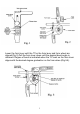
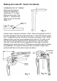
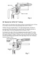
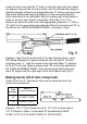
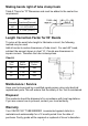
Table Of Contents

8
Lower the form lever until the “0” mark on the form lever and form wheel
are aligned, then pull the form lever down until the desired bend angle is
obtained. Degree of bend is indicated when the “0” mark on the form lever
aligns with the desired degree graduation on the form wheel(Fig.5A).
As an alternative to the calculation table for making right or left bends, a
scale on the form lever handle is provided. After mark “L”or “R” is
determined, place the mark even with appropriate graduation “L” (left) or
“R” (right) for the appropriate tube diameter.Place the second mark “B” on
the tube at the “HOOK ALIGNMENT MARK”, as shown in Fig.8.
Example—See Fig.8 for a bend left of the tube clamping hook, using
3/8" tubing Measure the required distance from the end of the tube
and place mark “L”. Hold the handle to the tube with Mark “L” adjacent
to the 3/8" Left mark. Make a second mark “B” on the tube adjacent to
the “HOOK ALIGNMENT MARK”. Place tube in bender with the second
mark “B” aligned with the right edge of the tube clamp hook (Fig.7).
Making bends left of tube clamp hook
Table1.This is for “L” Dimension and must be subtracted form the
center line requirement.
Tube
Diameter
Mark “B”
Fraction(Decimal)
3/8"
2-35/64" (2.546")
1/2"
2-29/32" (2.906")
Example: The “L” Dim.(Center line) is 9- 1/2" (9.5") and the tube is
1/2" O.D.Refer to Table 1 under Mark “B” and subtract 2-29/32"
(2.906").9-1/2" (9.5")-2-29/32"(2.906")=6-19/32"(6.594")