PM-2748-TL-SCL-LP INDICATOR USER’S MANUAL (Pallet Jack Indicator)
TABLE OF CONTENTS Safety Precautions 1 Preparations and Set Up 1 Features 2 Specifications 3 Power Supply 4 Display and Key Descriptions 5 Operating Instructions Calibration Indicator Parameter Settings 6-8 9-10 11-14 Helpful Definitions 15 Connectors 16 Troubleshooting 17 Contact Us 18
SAFETY PRECAUTIONS For safe operation of the weighing indicator, please follow these instructions: ●● Calibration inspection and maintenance of the indicator are prohibited by non-professional staff ●● Please ensure that the indicator rests on a stable surface ●● The indicator is a piece of static sensitive equipment; Please cut off power during electrical connections ●● Touching the internal components by hand is prohibited ●● DO NOT exceed the rated load limit of the unit ●● DO NOT step on the unit ●● DO
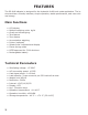
FEATURES The OP-918 indicator is designed for the hydraulic forlift truck scale application. The instrument has a friendly interface, simple operation, stable performance, and uses minimal energy.
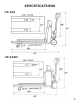
SPECIFICATIONS OP-918 OP-918M 3
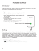
POWER SUPPLY AC Adapter Please use the included adapter to charge your indicator. We recommend to plug into a wall outlet to avoid interference with other wirings. Adapter 1. Connect adapter to indicator and plug into wall outlet 2. If adapter light is red, indicator needs to be charged 3. When indicator is completely charged, adapter light will turn green 4. Turn indicator on 5. An empty battery icon will flash for a couple seconds on indicator 6. This does NOT mean indicator is not charged 7.
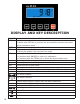
DISPLAY AND KEY DESCRIPTION ON/OFF Powers the Indicator On or Off if held for 3 seconds TOTAL 1. Accumulates weights 2. Works with SET key to perform the Accumulation function and check the Accumulation result UNIT Shifts between weighing units, KG and LB ZERO 1. Zero’s the scale within zero range 2. Tare’s the weight if its over the zero range SET 1. Long Press to print the weight 2. Combined with ON/OFF to enter into calibration 3.
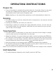
OPERATING INSTRUCTIONS Power On ●● Turn on the power by pressing the power button for 3 seconds. Once on, the scale will flash the voltage and then begin to auto-check and count down from 0-9 sequentially before entering the weighing mode Note: Anything on the scale before powering on will automatically be tared out.
Accumulation ●● The Accumulation function is used to add multiple weights and total them together ●● In weighing mode load the first weight, once stable press the TOTAL key to enter the Accumulation mode. The screen will show “n001” followed by the weight. ●● Remove the weight so scale reads 0 before adding the second weight to the scale ●● Once the second weight is stable press TOTAL key to add the weight to the Accumulated total, the screen will show “n002” followed by the weight.
Hold To use the hold feature press the SET and ZERO keys at the same time. Press both again to release the hold. There are 4 different hold functions you can choose from in the C11 parameter 1. Peak Hold: Grabs the highest weight (for materials testing, ie. tension and pulling force) ●● Press the HOLD key then add weight to the scale ●● The indicator will show the highest weight it recorded and hold it on the screen until a higher weight is placed on the scale 2.
PM-2746-TL-SCL-LP PALLET JACK CALIBRATION PROCEDURE 1. 2. 3. 4. 5. 6. 7. 8. 9. 10. 11. 12. 13. 14. 15. 16. 17. 18. 19. 20. 21. 22. 23. 24. 25. 9 Turn on the scale by holding ON/OFF for 2 seconds. and ON/OFF together to access the setup menu. Press and hold SET If done correctly, the display should now show C01. to access the C1 channel. The display should show [C1 1]. Press SET Press ZERO to choose which unit you want to calibrate in (1 = kg, 2 = lb). to set the value. The display will now show C02.
CALIBRATION cont. 26. Press SET to continue. The display will now show C07. to save and exit the setup menu. 27. Short press ON/OFF 28. The scale has now been calibrated. The display will show the value of the calibration weight on the scale. 29. If the scale does not show the value of the calibration weight, check that the pallet jack is level on the ground and on a flat surface and recalibrate 30. Unload the scale; the display should read 000000. If so, calibration is complete. 31.
INDICATOR PARAMETER SETTINGS The parameter settings menu has a calibration section (C01 to C07 explained above) and a parameter settings section (C08 and up). To enter calibration/parameter settings, follow the procedure below: 1. Press and hold the SET and ON/OFF key at the same time for 2 seconds 2. Navigate through the settings (C01 to C45) as shown in the table 4 below by using the arrow keys and return keys as labeled under each indicator button 3.
Function Parameter Settings/Options Automatic Power Off C09 Power Saving Mode C10 Hold Function C11 Inner Code Display C15 C16 C17 C20 Set Date Set Time Manual Zero Range Initial Zero Range C21 Zero Tracking C22 Zero Tracking Time C23 Overload Range C24 0 = turn off auto power off 10 = power off automatically if no change within 10 minutes 30 = power off automatically if no change within 30 minutes 60 = power off automatically if no change within 60 minutes LED Version OP918A: 0 = turn of
Function Parameter Settings/Options Negative Display C25 Standstill Time C26 Standstill Range C27 Digital Filter (for filtering moving weight such as animals) C28 Noise Filter C29 Gravity of Calibration Location Gravity of Destination C36 Version No. Print Mode Print Carriage Return Space Print Date Print Time Print 13 C37 C38 C41 C42 C43 C44 C45 0 = -9d 10 = -10% max. capacity 20 = -20% max. capacity 50 = -50% max. capacity 100 = -100% max.
Table 3.
HELPFUL DEFINITIONS Division: The amount of increments a scale offers. How accurate the scale can be Capacity: the maximum amount the scale can contain Initial Zero Range: The percentage of weight allowed on the scale when indicator is powered on that will automatically zero. example: If initial zero range is set to 10% of the max. capacity and your max. capacity is 100lbs, you can place up to 10lbs of weight on the scale and when the indicator is powered on, it will automatically zero out the weight.
CONNECTORS Connecting load cells to the indicator ●● ●● ●● ●● The indicator can connect with 4 load cells of 350Ω at most 4 wire or 6 wire load cell connections are both okay Please contact us directly if you have other special needs for your application There are two connection methods between the load cell and indicator Quick Disconnect as shown below: FIGURE 2: QUICK DISCONNECT CONNECTION DIAGRAM 16
TROUBLESHOOTING Error Codes Error Reason UUUUUU 1. Overload 2. Wrong connection with load cell 3. Load cell has quality problem nnnnnnn 1. Calibration is no good 2. Wrong connection with load cell 3. Load cell has quality problem ERR1 ERR3 During calibration, the input signal is negative ERR4 ERR5 ERR6 During calibration signal is unstable The calibration weight minimum is 10% of the max. capacity set in C04. Recommended to use 60%-80% of max. capacity if possible 1. Check all wire connections 2.