
Product Manual


5
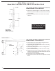
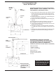
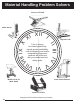
JIB CRANE IS SHIPPED IN 3 SECTIONS, HEAD ASSEMBLY,
BOOM ASSEMBLY, MAST ASSEMBLY, AND A BOX
CONTAINING BOLTS AND INSTRUCTIONS
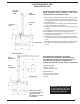
1) After foundation has hardened with anchor bolts set, install
leveling nuts (jam nuts) on anchor bolts and level across
nuts. Then fill center of bolt patter to top of leveling nuts, with
grout (Morta Mix).
2) Set mast into position on leveling nuts, install locking nuts
on top of anchor bolts and base plate.
3) Plumb the mast at 90° increments. Using the leveling nuts
to plumb.
4) Liberally grease the roller thrust bearing. The cone has
been installed at the factory inside to head assembly.
5) Lower head assembly onto mast assembly. Use care not to
damage roller thrust bearing.
6) Raise boom assembly onto head assembly. Attach with
4 - ASTM A325, 1/2" dia. bolts supplied. Torque bolts to 94
ft.-lbs.
7) After jib crane is operating satisfactorily set final grout under
base plate and let harden before placing jib crane into
service.
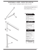
FLOOR MOUNTED JIBS
Model JIB-FM-3-80
WARNING! This equipment
is not designed for and
should not be supporting or
transporting personnel.
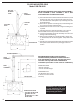
RECOMMENDED FOUNDATION CONCRETE
FOUNDATION REQUIREMENTS ARE BASED ON A
SOIL PRESSURE OF 2500 LBS. PER SQUARE FOOT
3000 LBS. PER SQUARE INCH COMPRESSIVE
CONCRETE (5 BAG MIX TO ONE YARD OF CONCRETE)
SPECIFICATIONS
• 300 lbs. Capacity
• 750 lbs. Overall Weight
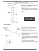
ANCHOR BOLTS
7/8" Diameter with J-Hook
5" Above Concrete Surface
15" Deep
ROLLER
BEARING
CONE
MAST
ASSEMBLY
LOCKING
NUTS
15
LEVELING
NUTS
42
18
1
FOUNDATION
4
42
15
15
42
FOUNDATION
MAST
ASSEMBLY
HEAD
ASSEMBLY
BOOM ASSEMBLY
4
42
18
15
REINFORCING BARS
- o 3/4 ROD ON BOTTOM
- o 5/8 ROD ON TOP
ON APPROX. 12" CTRS.
BOTH SIDES