
Product Manual


3
WARNING! This equipment
is not designed for and
should not be supporting or
transporting personnel.
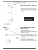
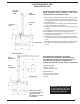
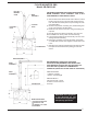
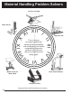
BOOM ASSEMBLY, UPPER SUPPORT ASSEMBLY & TIE
ROD ASSEMBLY FOR HIGH CEILING JIBS
(SHIPPED IN 3 SECTIONS)
1) Drill holes at desired height on a steel column using the
dimensions as shown. Make sure that the holes are centered
on the column.
2) Bolt the mounting brackets to the column with suitable
fasteners.
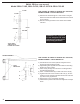
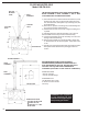
BOOM ASSEMBLY UPPER SUPPORT ASSEMBLY
& TIE ROD ASSEMBLY FOR HIGH CEILING JIBS
(SHIPPED IN 3 SECTIONS)
1) After brackets are mounted, (28-126-050) place thrust
bearing (A) under bearing boss (B).
2) Align bearing boss (B) with the holes inside the mounting
bracket (C) on the column.
3) Place rod (D) through the holes of the mounting bracket
and the bearing boss (B).
4) Place 1-1/8 flat washers (E) on both ends of the rod (D).
5) Tighten both ends of the rod with 1-1/8" nuts (F), be sure
that there is even amount of threads on both ends of the rod
(D). Allow a 1/4" gap between the bearing boss and the top
of the bracket.
6) Repeat steps 1-5 for the bottom assembly.
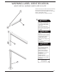
7) Align the pin holes of one yoke (H) to the pivot yoke brace
(J) and secure the clevis pin and cotter pin
8) Adjust yoke ends and tie rod (G) evenly to plump and level
the beam.
9) Then secure the other yoke (I) to the I-Beam with a clevis
pin and cotter pin
H
J
TIE ROD
ASSEMBLY
G
1
BOOM
ASSEMBLY
UPPER SUPPORT
ASSEMBLY
B
A
F
E
D
C
TIE ROD JIB (FOR HIGH CEILINGS)
Model JIB-HC-3-89, JIB-HC-6-89, JIB-HC-10-89 & JIB-HC-20-89
1-11/16"
1-11/16"
2
CENTER
37-5/8"
COLUMN
13/16" DRILL THROUGH
1ST FLANGE 12 PLACES
2
2
2