
Service manual
8
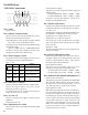
3-3: CE-22 “Common Data” (F2) Settings
Use the “CE22 /P” option when starting the
CE-22 Software.
PTT1 State: High
PTT2 State: High
Pre-emphasis: Off
De-Emphasis: On
EXT MIC Level: Low
EXT MOD Level: Low
4. VX-3000
(HARDWARE/SOFTWARE SETTINGS FOR VXR-1000)
4-1: VX-3000 Internal Jumpers
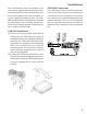
These jumpers configure the interconnec-
tions made via the D-sub 9-pin connector
on the rear of the VX-3000.
Note that the connections for the VX-3000L
(Low-Band) are different from those for the
VX-3000U.
VX-3000L JP1002 Open
JP1003 Jumper
JP1004 Open
JP1005 Jumper
JP1009 Open
JP1010 Jumper
VX-3000U JP1003 Open (RXD)
JP1004 Jumper (EXRA)
JP1005 Open (TXD)
JP1006 Jumper (EXM)
JP1009 Open
JP1010 Jumper
Connect a 10 kΩ resistor between Pin 1 and
Pin 8 at J1004 of the VX-3000; this is a pull-
up resistor for the Squelch line.
4-2: VX-3000 Software Settings in CE-19 for
PTT and MIC
These settings must be set appropriately
within CE19 in order for the VXR-1000 to
work correctly with the VX-3000.
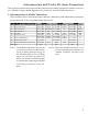
2. FTL-7011
(HARDWARE/SOFTWARE SETTINGS FOR VXR-1000)
2-1: VXR-1000 Internal Jumpers
POWER SUPPLY CONTROL: JP1001 Open
JP1002 Open
JP1003 Jumper
VXR-1000 OUTPUT: JP1004 Open
JP1005 Jumper
2-2: CE-22 “Common Data” (F2) Settings
Use the “CE22 /P” option when starting the
CE-22 Software.
PTT1 State: High (set to “Low” if con-
necting to the MUTE
connection at the base
of Q2005)
PTT2 State: Low (if no connection is
made to Pin 9 of J1004,
set to “High”)
Pre-Emphasis: Off
De-Emphasis: On
EXT MOD Level: Low
EXT MOD Level: Low
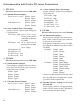
3. VX-2000
(HARDWARE/SOFTWARE SETTINGS FOR VXR-1000)
3-1: VX-2000 Internal Jumpers
These jumpers configure the interconnec-
tions made via the D-sub 9-pin connector
on the rear of the VX-2000.
JP1002 Open
JP1003 Jumper
JP1004 Jumper
JP1005 Open
3-2: VXR-1000 Internal Jumpers
POWER SUPPLY CONTROL: JP1001 Open
JP1002 Open
JP1003 Jumper
VXR-1000 OUTPUT: JP1004 Open
JP1005 Jumper
Interconnection with Vertex VX- Series Transceivers