
Service manual

29
Alignment
The VXR-1000 has been aligned at the factory
for the specified performance across the frequen-
cy range specified for each version.
Realignment should therefore not be neces-
sary except in the event of a component failure,
or after alteration of the repeater version. All
component replacement and service should be
performed only by an authorized Vertex repre-
sentative, or the warranty policy may be void-
ed.
The following test equipment is required for
alignment:
H IBM PC/compatible computer w/Vertex VPL-
1 cable, FRB-4, and CE-22 channel program-
ming diskette.
H RF signal generator: calibrated output level
at 1000 MHz (0 dBµ = 1.0 µV - closed circuit)
H Deviation meter (linear detector)
H AF millivoltmeter
H SINAD meter
H Inline wattmeter: 1000 MHz, 10 W scale
H Regulated DC power supply: adjustable from
10 to 17 V, 3 A
H 50-Ohm non-reactive dummy load: 10 W at
1000 MHz
H Frequency counter: 0.2 ppm accuracy at 1000
MHz
H AF signal generator
H DC Voltmeter: high impedance
H RF Sampling Coupler (attenuation pad)
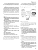
Before beginning, connect the transceiver and
PC using the VPL-1 cable and FRB-4 as shown
below, and download the EEPROM data from
the transceiver to the computer.
Store this data in a disk file so that it can be
saved and retrieved later. Using the table below,
program the channel, CTCSS, and DCS align-
ment settings for your transceiver version. Up-
load this file to the transceiver.
PLL & Transmitter
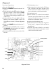
Set up the test equipment as shown for Align-
ment Setup. Adjust the supply voltage to 13.8 V
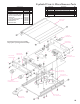
for all steps. Refer to the "Alignment Points" pho-
to for alignment locations.
PLL Reference Frequency
Ë Tune the transceiver to channel #3, connect
the sampling coupler and frequency counter
between the antenna connector and RF dum-
my load, key the transmitter, and adjust
TC2001 on the MAIN Unit for precisely 162.00
MHz (±100 Hz).
PLL VCV
Ë Leave the RF sampling coupler in-line between
the antenna jack and the RF dummy load.
Connect the frequency counter to the coupler.
Ë Connect the DC voltmeter between VCV test
point TP2006 on the MAIN Unit and chassis
ground.
Ë Set the transceiver to the low band edge chan-
nel #1. And adjust T2001 on the MAIN Unit
for 0.5 V on the voltmeter.
Ë Select high band edge channel #2. Key the
transmitter, and confirm the low-end VCV is
less than 4.4 V on the voltmeter.
RF Sampling
Coupler
RF Signal
Generator
50-Ohm
Dummy Load
Inline Wattmeter
Deviation Meter
Frequency
Counter
Power Supply
13.8V DC
VPL-1 Connection
Cable
COM port
FRB-4
Transceiver