
Security Camera User Manual

VerteX RTH Series H.8 and H.16 Series
13
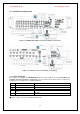
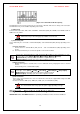
1. The input video type must be either NTSC or PAL; these two types must not be used
together.
2. Select the input video format (NTSC/PAL) using the CONFIG switch on the rear side of
the product.
3. Select the output monitor type (VGA/TV) using the CONFIG switch on the rear side of the
product.
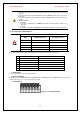
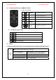
4. CONFIG SWITCH
1) VGA Mode
Resolution of VGA Monitor is SXGA (1280*1024) and CCTV Monitor output is not
supported.
2) TV Mode
Resolution of VGA Monitor SVGA (800 * 600) and CCTV Monitor output is supported.
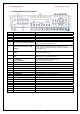
2-3-2. Connection of Other Devices
Difference between VERTEX RTH-Series and H.8 AND H.16-Series
ITEM VERTEX RTH-Series H.8 AND H.16-Series
Loop Out OK NO
Spot Out OK NO
Audio Channel 4 / 2 / 1 1 / 1 / 1
Sensor Channel 16 / 8 / 4 4 / 4 / 4
Relay Channel [1ea NC/NO] [3ea TTL Out] [1ea NC/NO]
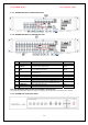
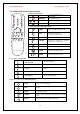
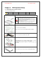
Connect the PTZ controller cable, audio input/output, network, and sensors as shown below.
Connected Device DVR Terminal
1
SPOT Monitor(CCTV Monitor) Rear SPOT
2
Mike / Speaker Rear Audio Input / Audio Output
3
LAN Cable Rear Ethernet
4
PTZ Camera Rear DIO (Digital Input/Output)
5
Sensor / Relay / TTL OUTPUT Rear DIO (Digital Input/Output)
6
Key controller Rear DIO (Digital Input/Output)
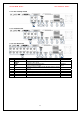
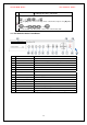
1) SPOT Monitor
Connect Spot Monitor to the rear SPOT terminal.
2) Audio Input/Output
Depending on models [VERTEX RTH-16 / VERTEX RTH-8 / VERTEX RTH-4 / H.8 AND H.16-Series], each of the
models supports [ 4 / 2 / 1 / 1] line input and 1 line output.
3) Terminal Block
[Figure 2-3. Terminal Block TB1]