
Security Camera User Manual

VerteX RTH Series H.8 and H.16 Series
10
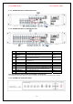
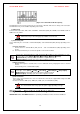
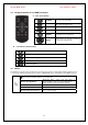
2-1-3. VERTEX RTH-Series 8 Channel Rear Part
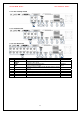
2-1-4. VERTEX RTH-Series 16 Channel Rear Part
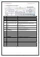
No. Name Feature Format
1 DC IN
Power cable connection to the body
2
NTSC/PAL
VGA/TV
Select the video input format
Select the video output format
DA-2
3
RS485
DIO
PTZ Camera Control Connection
Sensor/ Relay Connection
Terminal
Block
4 Ethernet
Network Connection(ADSL, Cable Modem, Ethernet
10/100 Base-T)
RJ-45
5 VGA-OUT
VGA Monitor or LCD Monitor Connection D-SUB 15P
6 AUDIO IN
Audio Input Connection(Line Only Input) RCA
7 AUDIO OUT
Audio Output Connection(Line Only Output) RCA
8 TV
CCTV Monitor Connection(Divided Screen) BNC
9 SPOT
CCTV monitor connection to output image from the
channel generating an event signal(Full Screen)
BNC
10 CAMERA IN
Video Camera Connection BNC
11 LOOP OUT
Video Signal loop-back Output Connection BNC
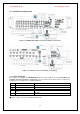
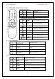
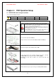
2-2. H.8 AND H.16-Series Name and Features of Each Part
The front part of SM-Series features an easy-to use button; various interfaces are located on the rear part.
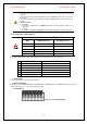
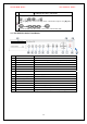
2-2-1. H.8 AND H.16-Series Front Panel