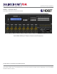
M U LT IM ED IA AUDIO A ND V IS UA L INSTRUCTION MANUAL MODEL : SB-5688LCM-CT 8x8 HDMI-HDBASET MATRIX SWITCHER 8x8 HDMI-HDBaseT Matrix Switch with Extension HDMI-HDBaseT MATRIX SWITCHER SERIES Thank you for purchasing the SB-5688CT HDMI-HDBaseT Matrix Switcher. You will find this unit easy to install and highly reliable but it is essential that you read this manual throughly before attempting to use 8x8 HDMIHDBaseT Matrix switcher.
SAFETY INFORMATION 1. To ensure the best results from this product, please read this manual and all other documentation before operating your equipment. Retain all documentation for future reference. 2. Follow all instructions printed on unit chassis for proper operation. 3. To reduce the risk of fire, do not spill water or other liquids into or on the unit, or operate the unit while standing in liquid. 4. Make sure power outlets conform to the power requirements listed on the back of the unit.
TABLE OF CONTENTS CONTENTS SAFETY PRECAUTIONS INTRODUCTION .............................................................. 1 PACKAGE CONTENTS .................................................... 2 Features ...................................................................... 2 Specifications ............................................................ 3 Front Panel ..................................................................4 Rear Panel ...............................................................
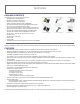
FEATURES PACKAGE CONTENTS Check that you have the following components; • SB-5688LCM-CT Matrix Switcher • RS-232 V2.0 Protocol Instructions • Ethernet V2.
SPECIFICATIONS Specifications • • • • • • • • • • • • • • • • • • • • • • Type of HDMI Switcher: 8x HDMI inputs To 8x HDMI + 8x HDBaseT Outputs Matrix Switcher HDMI Support: HD 1080p-@60Hz, H36-bit Deep color, 3D (1.4a) formats HDCP / CEC Support: HDCP 2.0 Compliant, CEC Compliant Video Bandwidth: Double Data Rates: 340Mhz, Total 6.
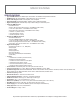
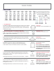
FRONT PANEL FRONT PANEL 1. POWER SWITCH The power switch turns the unit on and off. The LED will illuminate red to indicate that the switcher is ON and is receiving power. The Switcher will remember that last state during a power cycle. When power is removed and resorted, the last configuration will be evoked. 2. INPUT STATUS DISPLAY Input sources 1 to 8 LED illuminates blue to indicate that a video source is present on that input. 3.
FRONT PANEL FRONT PANEL 8. FUNCTION KEY - ALL Disables (mute) video on all destinations OR Selects the same source to all destinations. Option 1 - Press ALL followed by OFF button. The display will show “ 0 “ indicating all destinations have no video selected. Option 2 - Press ALL followed by Source 1 thru 8. The display will show the Source selected. - Press ENTER The pre-set source selection will be assigned all destinations. 9. FUNCTION KEY - OFF Disables (mute) video to selected channels.
FRONT PANEL FRONT PANEL 12. FUNCTION KEY - RECALL The system will show previously stored presets, up to a total of 16. Presets are stored in local memory using Source keys 1 thru 8 or Destination keys 1 thru 8 as the memory preset location. - Press RECALL button. - Press 1 thru 8 on either Source or Destination row. - Press ENTER The pre-set configuration will execute. Operation completes. Note: Operation will abort if no keys are dressed within 5 seconds. 13.
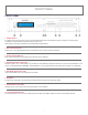
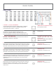
REAR PANEL REAR PANEL 1. DC POWER INLET The Switcher is fitted with a AC power plug input connector. Ensure that the used is of an approved type and is of sufficient current carrying connector capacity with the correct voltage and connector polarity. 1100~240Volt AC, 50/60Hz power supply. Power Plug: Power input - AC100~240V,50/60Hz, 10A 2. IR EXTENDER IN (EXT. IR TO CONTROL SWITCHER) Support one of IR Extender to control Switcher. Extend distance maximum 300M / ~1000 ft.
REAR PANEL REAR PANEL 6. OUTPUT - 1,2,3,4,5,6,7 & 8 HDBaseT CAT Transmitter extend a signal link of HDMI / RS232 / IR Remote to this RJ-45 Female connector via CATX(6/6a) category cable. Connector with RJ-45 Output 1 ~ Output 8 HDBaseT Phone-Jack 8P8C Connector: RJ-45 Female connector. 7. HDBaseT RS-232 - 1,2,3,4,5,6,7 & 8 CONNECTION (8)x RS-232 control port to allow for interfacing to a PC. Controls I/O via Switcher HDBaseT Transmitter (8) Rooms each.
REMOTE CONTROL Before making any connections to the switcher. Observe the following: > Ensure the mains voltage supply matches the label on the supplied plug-pack (+/- 10%) > Connect all audio video sources and destination equipment > Ensure that the power switch is OFF > For each destination output select the appropriate input source by using the front panel input 1~8 select buttons. The supplied IR remote control. Or through the RS-232 serial communications port.
REMOTE PROTOCOL COMMANDS IR REMOTE CUSTOM AND DATA CODES (NEC Standard) HOW TO SETUP IR CODES : CUSTOM CODE : 09F6 ALL OFF EDID LOCK RECALL MEMORY ENTER POWER ON : 09F6 A15E POWER OFF : 09F6 A25D : 09F6 B04F : 09F6 B14E : 09F6 B748 : 09F6 B54A : 09F6 B24D : 09F6 B44B : 09F6 B34C PRESS DESTINATION - # then PRESS SOURCE - # DESTINATION #1 : 09F6 DESTINATION #2 : 09F6 DESTINATION #3 : 09F6 DESTINATION #4 : 09F6 DESTINATION #5 : 09F6 DESTINATION #6 : 09F6 DESTINATION #7 : 09F6 DESTINATION #8 : 09F6 SOURCE
REMOTE CONTROL ROOM REMOTE CONTROL #1 ~ #8 CUSTOM CODE AND DATA CODES IR CUSTOM AND DATA CODES (NEC Standard) PRESS Number To Select SOURCE CUSTOM CODE : 09F6 IR-01 DATA CODE: IR-02 DATA CODE: SOURCE #1 : 09F6 11EE SOURCE #1 : 09F6 SOURCE #2 : 09F6 12ED SOURCE #2 : 09F6 SOURCE #3 : 09F6 13EC SOURCE #3 : 09F6 SOURCE #4 : 09F6 14EB SOURCE #4 : 09F6 SOURCE #5 : 09F6 15EA SOURCE #5 : 09F6 SOURCE #6 : 09F6 16E9 SOURCE #6 : 09F6 SOURCE #7 : 09F6 17E8 SOURCE #7 : 09F6 SOURC
REMOTE CONTROL ROOM REMOTE CONTROL #1 ~ #8 CUSTOM CODE AND DATA CODES IR CUSTOM AND DATA CODES (NEC Standard) PRESS Number To Select SOURCE CUSTOM CODE : 09F6 IR-05 DATA CODE: IR-06 DATA CODE: SOURCE #1 : 09F6 51AE SOURCE #1 : 09F6 SOURCE #2 : 09F6 52AD SOURCE #2 : 09F6 SOURCE #3 : 09F6 53AC SOURCE #3 : 09F6 SOURCE #4 : 09F6 54AB SOURCE #4 : 09F6 SOURCE #5 : 09F6 55AA SOURCE #5 : 09F6 SOURCE #6 : 09F6 56A9 SOURCE #6 : 09F6 SOURCE #7 : 09F6 57A8 SOURCE #7 : 09F6 SOURC
EDID FUNCTION EDID function for HDMI Matrix Switcher EDID Setup To Change the EDID Setup Step 1. Press the EDID button The display will show the currently selected EDID mode Step 2. Press SOURCE #1 or #2 button row The button will flash blue and the display will show the current Embedded EDID Status. Step 3. Press the ENTER button To set EDID mode. The switcher will return to operation mode. Operation will abort if no keys are pressed within 5 seconds.
EDID FUNCTION NOTE : The already learned EDID cannot be modified. You can only rebuild a new Learning EDID. For example: When the Source has “Learned” the EDID data from a destination, It will save that EDID information into EPROM and the EDID data cannot change. Please select new learning destination to sources or change to one of the embedded EDID modes when you want to remove the learning EDID memory from EPRPM. Mode 1. FSS (Fast Speed Start) Mode 5.
EDID FUNCTION EDID function for HDMI Matrix Switcher EDID Status To view the current EDID status. Step 1. Press EDID button The button will flash blue and the display will show the current Embedded EDID Status. Step 2. Press EDID button To exit. How to setup FSS Function Fast Speed Start Step 1. Press the Destination #1~8 button row To setup and Install all devices. Step 2. Press EDID button Select a optimum status of Embedded EDID mode. Step 3. Press ENTER button To conform entries Step 4.
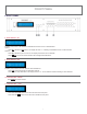
TYPICAL APPLICATION INSTALLING DIAGRAM Sample connection using IR Transmitters (SB-101) and IR Receiver (SB-100) with SB-6335R & SB-5688LCM-CT to control a projector. NOTE: 1. IR Control Projector Over HDBaseT Extender: SB-5688LCM-CT HDBaseT Transmitter SB-6335R HDBaseT Receiver 2. Projector RS-232 Control by a PC via CATx TX. 3. Projector IR control via CATx IR in (IR to projector). 4. IR Extender Transmitter (SB-101): Use SB-101 IR Transmitter to Extend IR signal to Projector. 5.
TYPICAL APPLICATION INSTALLING DIAGRAM Sample connection using IR Transmitters (SB-101) with SB-5688LCM-CT and SB-6335R to control a IR signal from Satellite Receiver. NOTE: 1. IR Control Satellite Receiver Over HDBaseT CAT5e/6/7 Extender from room: SB-5688LCM-CT HDBaseT CAT5e/6/7 Transmitter SB-6335R HDBaseT CAT5e/6/7 Receiver 2. Destination RS-232 Control : Via SB-5688LCM-CT TX RS-232 in. 3.
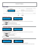
TYPICAL APPLICATION INSTALLING DIAGRAM Sample connection using Audio Extractor to Recode Audio (SB-5609) or to control ARC (SB-5610) and Extend the HDMI signal via HDBaseT Transmitter to IR Receivers (SB-6335R) with SB-5688LCM-CT to extend 100M distance between switcher and destination. NOTE: 1. Audio Extractor To Recode Audio : SB-5609 HDMI Audio Extractor. 2. Control HDMI ARC: SB-5610 ARC Control Box. 3. Switcher RS-232 Control Via a PC. 4. Switcher IR External port : Via SB-100 IR Extender Receiver. 5.
IR EXTENDER IR RECEIVER: 1. SB-100 IR 300M Receiver Device Cable (3C) IR Receiver (SB-100) R oHS /95/E C IR E XT. in RS - 232 IR EXT . INP UT DC 12V 3 4 4 R S -232 4 3 UT 4 -2 3 -4 UT IR 2 R IX IN P I MAT SW 1 HDM 1 S WIT UT 2 IN P 1 C HE -3 R 3 UT ER 2 P OW IN P 2 ON 1 IN P OFF -1 IR Rx SB-100 SB-100 IR Receiver Set 2.
IR EXTENDER IR EMITTER: 1. SB-101 IR 300M Transmitter DC 12V Device Cable (3C) IR out IR in CAT6/6a/7 From Receiver To Receiver OUTPUT IR Transmitter (SB-101) R oHS /95/E C IR Tx SB-101 SB-101 IR Transmitter Set 2.
RS-232 SERIAL INTERFACE RS-232 SERIAL INTERFACE CONNECT a PC or CONTROL SYSTEM. VERSION COMPATIBLE V1.0 & V1.5 For a complete list of commands, please reference external document extended RS-232 Protocol Instruction Manual.
ETHERNET SERIAL INTERFACE ETHERNET SERIAL INTERFACE CONNECT a PC or CONTROL SYSTEM. VERSION COMPATIBLE V2.0 For a complete list of commands, please reference external document extended Ethernet Protocol Instruction Manual.
LIMITED WARRANTY PLEASE READ THE FOLLOWING TERMS AND CONDITIONS CAREFULLY BEFORE USING THIS HARDWARE, COMPONENTS AND SOFTWARE PROVIDED BY, THROUGH OR UNDER SHINYBOWUSA, INC (COLLECTIVELY, THE “PRODUCT”). By using installing or using the Product, you unconditionally signify your agreement to these Terms and Conditions. If you do not agree to these Terms and Conditions, do not use the Product and return the Product to SHINYBOWUSA, Inc.
M U LT IM ED IA AUDIO A ND V IS UA L www.shinybowusa.com 1399 Wildfire Lane | Frisco, TX 75034 1-877-SHINY-USA 1-877-744-6987 1-972-377-2508 sales@shinybowusa.