with Metallic Center Section 3: EXP VIEW 2: INSTAL & OP 1: PUMP SPECS V4 Metallic Pumps • Aluminum • Cast Iron • Stainless Steel 4: WARRANTY Service & Operating Manual Original Instructions Versa-Matic V4 1¼" V Series Clamped Metallic - See E5PPxxxx9C Exploded - REV REVISION CHG VERSA-MATIC® • Warren Rupp, Inc. • A Unit of IDEX Corporation 800 North Main Street, Mansfield, OH 44902 USA • Phone: (419) 526-7296 • www.versamatic.com © Copyright 2014 Warren Rupp, Inc.
Safety Information IMPORTANT WARNING When used for toxic or aggressive fluids, the pump should always be flushed clean prior to disassembly. Read the safety warnings and instructions in this manual before pump installation and start-up. Failure to comply with the recommendations stated in this manual could damage the pump and void factory warranty. Before maintenance or repair, shut off the compressed air line, bleed the pressure, and disconnect the air line from the pump.
SECTION 2: Installation & Operation.......8 • Principle of Pump Operation • Typical Installation Guide • Troubleshooting SECTION 3: Exploded View..........................11 • Composite Drawings • Parts List • Materials Code 4: WARRANTY 3: EXP VIEW SECTION 4: Warranty & Certificates.....15 • Warranty • EC Declaration of Conformity - Machinery 2: INSTAL & OP SECTION 1: Pump Specifications.................
Explanation of Pump Nomenclature Your Serial #: (fill in from pump nameplate)______________________________________ 1: PUMP SPECS Your Model #: (fill in from pump nameplate) Model #: __ __ __ __ __ __ __ __ __ __ __ __ VERSA-MATIC® MODEL IDENTIFICATION CODES __ X X X X X X X X X X - X X X Options (if applicable) Revision Level Construction Design Valve Seat Material/Valve Seat O-ring Material Valve Ball Material Diaphragm Series Diaphragm Material Non-Wetted Parts Wetted Parts Pump Size Mo
Material Profile: Operating Temperatures: CAUTION! Operating temperature limitations are as follows: Max. Min. Conductive Acetal: Tough, impact resistant, ductile. Good abrasion resistance and low friction surface. Generally inert, with good chemical resistance except for strong acids and oxidizing agents. 190°F 88°C -20°F -29°C EPDM: Shows very good water and chemical resistance. Has poor resistance to oils and solvents, but is fair in ketones and alcohols.
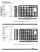
Performance Flow Rate Adjustable to . . . . . . . 0-61 gpm (230.9 lpm) Port Size Suction . . . . . . . . . . . . . . . . . . . . 1 1/4" NPT Discharge . . . . . . . . . . . . . . . . . . . . 1 1/4" NPT Air Inlet . . . . . . . . . . . . . . . . . . . . . 3/8" NPT Air Exhaust . . . . . . . . . . . . . . . . . 3/4" NPT Suction Lift Dry . . . . . . . . . . . . . . . . . . . . . . . 20' (6.09 m) Wet . . . . . . . . . . . . . . . . . . . . . . 25' (7.62 m) Max Solid Size (Diameter) . . . . . . . . . . . .
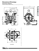
Dimensional Drawings 8 6 7 V4 Aluminum Clamped 4 5 3 Dimensions in inches (mm dimensions in brackets) The dimensions on this drawing are for reference only. A certified drawing can be requested if physical dimensions are needed. 12.32 [312.93] 14.36 [364.74] 1 1/4" NPT / BSP TAPERED DISCHARGE PORT 1: PUMP SPECS D 11.50 [292.09] 1/2" NPT AIR INLET C 17.11 [434.59] 8.78 3 [223.01] 2 1 3/4" NPT AIR EXHAUST 2.55 [64.77] 4.57 [116.08] .31 [7.87] B 2.20 [55.
7 Dimensional Drawings 6 4 5 3 V4 Screen Mounted Dimensions in inches (mm dimensions in brackets) The dimensions on this drawing are for reference only. A certified drawing can be requested if physical dimensions are needed. D 1: PUMP SPECS C 12.32 [312.93] 14.36 [364.74] 1 1/4" NPT / BSP TAPERED DISCHARGE PORT 11.50 [292.09] 1/2" NPT AIR INLET 17.14 [435.36] 2 3 8.81 [223.77] 1 3/4" NPT AIR EXHAUST B 4.59 [116.6] D 7.70 [195.58] 13.50 [342.90] A 4.53 [115.
Dimensional Drawings 8 7 6 4 5 V4 Cast Iron Clamped Dimensions in inches (mm dimensions in brackets) The dimensions on this drawing are for reference only. A certified drawing can be requested if physical dimensions are needed. 12.32 [312.93] D 11.50 [292.10] 1 1/4" NPT / BSP TAPERED DISCHARGE PORT 1: PUMP SPECS 14.40 [365.76] 1/2" NPT AIR INLET 16.88 [428.75] C [ 8.84 [224.53] 2 3 1 3/4" NPT AIR EXHAUST 2.63 [66.8] 4.63 [117.6] .50 [12.
8 6 7 Dimensional Drawings 4 5 V4 Stainless Clamped Dimensions in inches (mm dimensions in brackets) The dimensions on this drawing are for reference only. A certified drawing can be requested if physical dimensions are needed. D 1: PUMP SPECS 14.19 [360.43] 12.32 [312.93] 1 1/4" NPT / BSP TAPERED DISCHARGE PORT 11.50 [292.1] 1/2" NPT AIR INLET C 16.76 [425.70] 2 8.72 3 [221.49] B 1 3/4" NPT AIR EXHAUST 2.55 [64.77] 4.51 [114.55] .31 [7.87] D 1.88 [47.
Principle of Pump Operation Air-Operated Double Diaphragm (AODD) pumps are powered by compressed air or nitrogen. The main directional (air) control valve ① distributes compressed air to an air chamber, exerting uniform pressure over the inner surface of the diaphragm ②. At the same time, the exhausting air ③ from behind the opposite diaphragm is directed through the air valve assembly(s) to an exhaust port ④. Discharged Fluid The pump primes as a result of the suction stroke.
Recommended Installation Guide Available Accessories: 1. Surge Suppressor 2. Filter/Regulator 3. Air Dryer Unregulated Air Supply to Surge Suppressor 1 Surge Suppressor Pressure Gauge Shut-Off Valve Note: Surge Suppressor and Piping must be supported after the flexible connection.
Troubleshooting Guide Pump Cycles Once Pump Will Not Operate / Cycle Pump Cycles and Will Not Prime or No Flow Potential Cause(s): Deadhead (system pressure meets or exceeds air supply pressure). Air valve or intermediate gaskets installed incorrectly. Bent or missing actuator plunger. Pump is over lubricated. Lack of air (line size, PSI, CFM). Check air distribution system. Discharge line is blocked or clogged manifolds. Deadhead (system pressure meets or exceeds air supply pressure).
Composite Repair Parts Drawing - PTFE 6 66 3737 37 1515 15 8 88 3838 38 5 55 8 37 15 1010 10 6 37 15 38 6 5 8 38 5 3535 35 MAIN SHAFT MAIN SHAFT MAIN SHAFT SEAL LOCATIONS SEAL LOCATIONS SEAL LOCATIONS 4 44 10 7 77 3636 36 10 7 8 13 2828 28 1818 18 2222 22 2 24 23 25 24 16 6 5 711 77 12 8 88 2121 21 17 2020 20 17 4 3434 34 26 2727 27 3: EXP VIEW 8 21 3030 30 3131 31 27 WARREN WARREN RUPP INC. WARRENRUPP RUPPINC. INC. THIS IS A PROPRIETARY DOCUMENT.
Composite Repair Parts List - PTFE Item # Qty. 1 2 3 4 5 6 7 8 9 10 11 12 1 1 1 1 1 1 2 1 1 1 4 Item # 13 14 15 16 17 18 19 20 21 Qty. 1 5 2 2 3 3 1 1 Item # 22 23 24 25 26 27 28 29 30 Qty. 1 2 2 2 2 2 4 4 4 Item # Qty.
Composite Repair Parts Drawing - Rubber 6666 35 35 35 35 15 15 15 15 8888 36 36 36 36 5555 31 31 31 31 10 10 10 10 6 35 15 8 35 15 36 36 MAIN SHAFT MAIN MAIN MAIN SHAFT SHAFT SHAFT SEAL LOCATIONS SEAL SEAL SEAL LOCATIONS LOCATIONS LOCATIONS 11 11 11 11 6 5 8 5 33 33 33 33 4444 11 8888 26 26 26 26 11 33 34 8 28 28 28 28 25 25 25 25 16 5 16 2 5 23 26 30 22 18 22 17 4 32 32 32 32 7 3: EXP VIEW 4 8 28 28 28 28 21 20 32 37 37 37 37 WARREN RUPP INC.
Composite Repair Parts List - Rubber Item # Qty. Description 1 2 3 4 5 6 7 8 9 10 11 12 1 1 1 1 1 1 2 1 1 1 4 Valve Body ASY (includes items 4-11) Oil Bottle Lubricator Rod Valve Body Valve Spool End Cap with Guide End Cap without Guide Snap Ring Air Valve Gasket Reducer Bushing Air Valve Screen Air Valve Mounting Bolt Item # 13 14 15 16 17 18 19 20 21 Qty. 1 5 2 2 3 3 1 1 Item # 22 23 24 25 26 27 28 Qty. 1 2 2 2 4 4 4 Item # Qty.
Written Warranty 5 - YEAR Limited Product Warranty Quality System ISO9001 Certified • Environmental Management Systems ISO14001 Certified Versa-Matic warrants to the original end-use purchaser that no product sold by Versa-Matic that bears a Versa-Matic brand shall fail under normal use and service due to a defect in material or workmanship within five years from the date of shipment from Versa-Matic’s factory. ~ See complete warranty at http://www.versamatic.com/pdfs/VM%20Product%20Warranty.