
Operating instructions

24 20300293
Resolution Direct Vent Gas Fireplace
1. This should be done before framing the replace.
Wire the receptacle into an electrical circuit. Wire with
minimum 60° C wire in accordance with prevailing
codes.
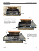
2. Remove the external junction box cover by removing
the screw from the side of the outside rebox wall.
Junction box was installed at the factory.
3. The junction box cover has a factory installed “ro-
mex” style strain relief connector. After connecting
the wires, route the wire leads through this connector.
Refer to the wiring diagram in Figure 30.
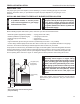
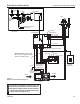
Figure 30 -
Junction Box Wiring Diagram
FP1912
Junction box wiring
8/08
Junction Box
Factory Supplied
Not Supplied
120V AC
60Hz
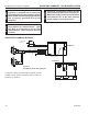
The command center may be mounted on the wall with
the use of the SCSWEK Kit (15ft. cable, junction box,
wall cover).
Mount the junction box provided at the desired location
on the wall. Do not extend beyond the 15 ft. wire cable
provided. If a longer distance is required, the 15 ft. may be
extended up to 30 ft. maximum by using two (2) SCSWEK
cables plugged together.
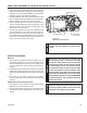
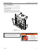
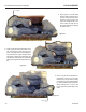
Route the wire from junction box to lower control area
at bottom of replace. Unplug the 12" cable from the
command center. Attach the connector to the pins from
wire by pushing in to connector making sure to follow the
color code on connector. Plug the 15 ft. extension cable
into the 2 ft. cable. Remove command center from the
replace and plug the other end of the extension cable
into the command center. Snap on wall cover provided
and screw to junction box.
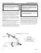
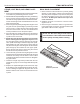
The wall switch wire connection is located off the 2 ft.
wire harness from the control box to the command center.
Figure 31. The connection is labeled “Wall Switch”. Unplug
the male and female connectors and connect the two (2)
low voltage wires provided. Run wire to desired location
on wall. Up to 50 ft. of 18 ga. wire may be used if neces-
sary. Attach wires to wall switch. Mount the wall switch in
to junction box and screw on cover.