
Operating instructions


18
20304166
VCFDVI31 Gas Fireplace Insert
The intake/exhaust manifold is shipped attached to insert.
It may be removed to allow tight installation.
1. Unfasten the two (2) machine screws on the face of the
unit and release the plate assembly by sliding the plate
back.
2. Attach the exhaust and the intake ex pipes to the collar
on the plates with a hose clamp (not provided) or other
approved methods (check local codes).
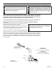
The unit is shipped from the factory as a natural gas unit
with the bafe installed. The bafe should be sufcient for
venting up to 20 feet (6 m) off the top of the unit. An extra
bafe plate is shipped with the unit for installations of 20
feet and above.
Remove four (4) screws holding bafe plate. Add extra
bafe pate and reinstall screws. Align slots in bafe plates
so the slots are closed. Retighten screws.
For propane (LP) units the bafe assembly is com-
pletely removed for venting under 20 ft. (6 m). For venting
20 ft. and above, the bafe assembly is to be used with
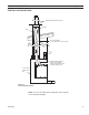
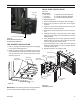
only one (1) bafe plate installed. Figure 26
FP1961
baffle adjustment
9/08
Loosen Four (4) Screws to Adjust
FP1961
Figure 26 -
Bafe Assembly and Adjustment
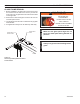
3. Slide plate assembly back in place under locating
tabs.
4. While sliding unit in place, if necessary the glass latch/
shutoff tool can be used to help place the plate assem-
bly. Using the small end of the tool, insert it in the square
notch in top front of rebox. Hook the plate assembly
with tool and pull forward into place while sliding rebox
to the rear. Figure 25
5. Reinstall and tighten machine screws.
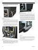
FP2977
latch tool plate assy
Plate
Assembly
Latch Tool
FP2977
Figure 25
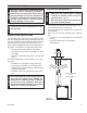
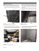
FP2979
intake exhaust
Figure 24
Machine
Screws
Intake Collar
Exhaust/Intake
Slide Plate
Assembly
FP2979
Exhaust Collar