INSTALLER / CONSUMER SAFETY INFORMATION PLEASE READ THIS MANUAL BEFORE INSTALLING AND USING APPLIANCE. WARNING! IF THE INFORMATION IN THIS MANUAL IS NOT FOLLOWED EXACTLY, A FIRE OR EXPLOSION MAY RESULT CAUSING PROPERTY DAMAGE, PERSONAL INJURY OR LOSS OF LIFE. FOR YOUR SAFETY Installation and service must be performed by a qualified installer, service agency or the gas suppler.
Stardance Direct Vent/Natural Vent Gas Heater Table of Contents PLEASE READ THE INSTALLATION & OPERATING INSTRUCTIONS BEFORE USING APPLIANCE. Thank you and congratulations on your purchase of a Vermont Castings stove. IMPORTANT: Read all instructions and warnings carefully before starting installation. Failure to follow these instructions may result in a possible fire hazard and will void the warranty. 2 Installation & Operating Instructions ................................................................
Stardance Direct Vent/Natural Vent Gas Heater General Information The Stardance Direct Vent/Natural Vent Room Heater, Model Nos. 3900-3916, 3940-3956 is a vented gas appliance listed to the ANSI standard Z21.88b-2002 and CSA-2.33b-2002 for Vented Room Heaters, and CSA 2.17-M91, Gas-Fired Appliances For Use at High Altitudes. The installation of the Stardance Direct Vent/Natural Vent Room Heater must conform with local codes, or in the absence of local codes, with National Fuel Gas Code, ANSI Z223.
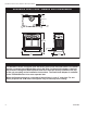
Stardance Direct Vent/Natural Vent Gas Heater Stardance Direct Vent / Natural Vent Dimensions 9" (229 mm) CL Valve Inlet 26���" (680 mm) Valve Inlet CL 3" (76 mm) 14���" (355 mm) 25" (635 mm) 7065 Attention Stardance fully assembled The Stardance stove is shipped from thedimensions factory as a Direct Vent Gas Heater. This heater in the field.
Stardance Direct Vent/Natural Vent Gas Heater Installation Requirements The installation must conform with local codes or, in the absence of local codes, with the National Fuel Gas Code, ANSI Z223.1/NFPA 54 - latest edition. (EXCEPTION: Do not derate this appliance for altitude. Maintain the manifold pressure at 3.5 inches w.c. for Natural Gas, and 10 inches w.c. for Propane). In Canada, installation must be in accordance with the current CSA B-149.1 Installation Codes and/or local codes.
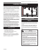
Stardance Direct Vent/Natural Vent Gas Heater Parallel Installation: Minimum Clearance and Flue Centerline, Direct Vent and Natural Vent Wall Centerline from Floor Direct Vent Only C L C A D A C L B ST131b ST128b Stove Clearances: A: 4” (102 mm) B: 4” (102 mm) Pipe Centerlines: C: 15¹⁄₂” (395 mm) ST128b D: 9” (229 mm) Fig. 3 Parallel installation, minimum back and side clearStardance ances, and flue centerlines.
Stardance Direct Vent/Natural Vent Gas Heater Gas Specifications Weight: Fully assembled; 202 lbs. Gas Inlet and Manifold Pressures Inlet Minimum Inlet Maximum Manifold Pressure Natural 5.5” w.c. 14.0” w.c. 3.5” w.c. LP (Propane) 11.0” w.c. 14.0” w.c. 10” w.c. Stardance Direct Vent / Natural Vent Certified to: ANSI Z21.88-2005 / CSA 2.
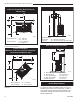
Stardance Direct Vent/Natural Vent Gas Heater Vent Termination Clearances Vertical Termination - Direct Vent ONLY A vertical vent system must terminate no less than 8’ (2.44m) and no more than 40’ (12m) above the appliance flue collar. A 2Z\v” restrictor plate (supplied) must be used where specified in all vertically terminated vent systems. (Fig. 8) NOTE: The restrictor plate supplied with the vertical termination should be discarded. Install restrictor plate supplied with stove directly at stove outlet.
Stardance Direct Vent/Natural Vent Gas Heater Vent Termination Clearances Your stove is approved to be vented either through the side wall, or vertical through the roof. • CFM Corporation does not require any opening for inspection of vent pipe. • Only CFM Corporation and Simpson DuraVent venting components specifically approved and labelled for this stove may be used. • Minimum clearances between vent pipes and combustible materials is one (1”) inch (25 mm), except where stated otherwise.
Stardance Direct Vent/Natural Vent Gas Heater General Venting Information - Termination Location INSIDE CORNER DETAIL G V H A N N D L V E C B V F B ����� ������ B V Ope Operable rable V B B V B J X X AIR SUPPLY INLET M I A CFM145a V VENT TERMINATION V Fixed Closed C = Clearance to permanently closed window D = Vertical clearance to ventilated soffit located above the terminal within a horizontal distance of 2’ (610mm) from the center line of the terminal E = Clearance to unven
Stardance Direct Vent/Natural Vent Gas Heater Termination Clearances Termination clearances for buildings with combustible and noncombustible exteriors. Inside Corner Alcove Applications* Outside Corner G= Combustible 6" (152 mm) G F= Combustible 6" (152 mm) Noncombustible 2" (51 mm) V Noncombustible 2" (51 mm) V C V E O F Balcony with perpendicular side wall Balcony with no side wall D C E = Min. 6” (152 mm) for non-vinyl sidewalls Min. 12” (305 mm) for vinyl sidewalls O = 8’ (2.4 m) Min.
Stardance Direct Vent/Natural Vent Gas Heater Venting Requirements and Options Direct Vent ONLY Approved Vent System Components The Stardance Heater must be vented to the outdoors through an adjacent exterior wall or through the roof. The venting system must be comprised of the appropriate listed venting components specified on this page. These parts are available from DuraVent Corporation or your Vermont Castings Dealer. See Figure 4 for dimensions relevant to the standard minimum-vent kits.
Stardance Direct Vent/Natural Vent Gas Heater Install the Optional Fan If you are installing the optional convection Fan Kit #2767 (FK26), continue here. If you are not installing a Fan Kit, go to Page 14, Venting System Assembly. 1. The fan kit includes a Blower Assembly and a Rheostat Assembly, connected by a cable. (Fig. 12) The Blower Assembly mounts to the bottom rear of the stove, and the Rheostat mounts to the valve bracket to the left of the valve.
Stardance Direct Vent/Natural Vent Gas Heater Venting System Assemlby - Direct Vent General Information First Section of Vent Pipe The Stardance is approved for installation only with the vent components listed on Page 12. Follow the vent component instructions exactly. For U.S. installations: The venting system must conform with local codes and/or the current National Fuel Gas Code, ANSI Z223.1/NFPA 54. For Canadian installations: The venting system must conform to the current CSA B149.
Stardance Direct Vent/Natural Vent Gas Heater Install the Vent Adapter Pipe Side Wall Termination Assembly (Simpson Dura-Vent Components) 1. Install the Restrictor Plate. Consult the ‘Vent Run Specifications’ on Page 8 to determine whether the restrictor plate is needed. If so, put the restrictor plate in place within the inner flue collar. (Fig. 16) 2. Discard the inner starter pipe shipped with the logset. Using the starter pipe assembly listed on Page 7, slide the inner section out to allow access.
Stardance Direct Vent/Natural Vent Gas Heater For DuraVent pipe only: Install vent pipe by aligning the locking system together, sliding the pipes together and twisting clockwise. • Install 90° elbow. Twist lock as before. • Slide the wall plate over horizontal run before attaching the horizontal run to the elbow. Fasten wall plate to wall. 4.
Stardance Direct Vent/Natural Vent Gas Heater Vent Termination Below Grade Recessed Wall Install Snorkel Kit #7FSDVSKS when it is not possible to meet the required vent termination clearances of 12” (305mm) above grade level. The snorkel kit will allow installation depth of down to 7” (178mm) below grade level. The seven inches is measured from the center of the horizontal vent pipe as it penetrates the wall.
Stardance Direct Vent/Natural Vent Gas Heater 9. Install the storm collar and seal around the joints. (Fig. 31) 10. Add additional vent lengths to achieve the proper overall height. 11. Apply cement to the inner and outer termination collars and install the terminal cap. #7DVAIS Attic Insulation Shield #7DVFS Firestop in Upper Floor Use Four 8dNails Venting System Assembly - Natural Vent General Information The Stardance Heater is shipped from the factory as a Direct Vent Heater.
Stardance Direct Vent/Natural Vent Gas Heater Install the Vent Pipe Apply a bead of sealant around bottom end of inner starter pipe (found in bag with logset) and attach to stove. Apply a bead of sealant around top of inner starter pipe and install the Z31D00 FSDHAG Draft Hood according to Draft Hood instructions. (Fig. 33) Attach the first section of venting to the draft hood.
Stardance Direct Vent/Natural Vent Gas Heater In the U.S.; Gas connection should be made in accordance with current National Fuel Gas Code, ANSI Z223.1/NFPA 54. Since some municipalities have additional local codes, be sure to consult your local authority. In Canada; consult the local authority and CSA-B149.1 installation code. Always check for gas leaks with a mild soap and water solution. Do not use an open flame for leak testing.
Stardance Direct Vent/Natural Vent Gas Heater 8. The air shutter is located on the bottom of the burner to the left. Unfasten the two nuts holding the shutter in place. The shutter may be adjusted between the factory adjusted 1/2” to fully open. Reassemble the shutter to allow the rear injector air inlet to close from the minimum 1/2” opening to fully open. (Fig. 39) You may have to try more than once to find the correct air shutter opening for best results depending on your altitude.
Stardance Direct Vent/Natural Vent Gas Heater Thermostat Connection (optional) Use only a thermostat rated for 500 millivolts. Check the table below for the appropriate gauge thermostat wire to use for the length of lead required in your installation. Thermostat Wire / Gauge Maximum Run 18 20 feet 16 20 - 40 feet 14 up to 60 feet 1. Install the wall thermostat in the desired location and run the wires to the stove location. Terminate these leads with 1/4” female connectors. 2.
Stardance Direct Vent/Natural Vent Gas Heater Operation The Stardance is operated with the operable door front plate in place with the doors open or closed. To open the front doors, insert the handle into the door latch stub and turn it to the left and up. (Fig. 44) When not in use, the handle may be stored in the handle holder on the right side of the rear shroud. (Fig. 47) Clockwise to Open ST476 Fig. 46 Pilot assembly location. ST477 Flame & Temperature Adjustment Stardance ST621 Fig.
Stardance Direct Vent/Natural Vent Gas Heater Lighting and Operating Instructions FOR YOUR SAFETY READ BEFORE LIGHTING WARNING:If you do not follow these instructions exactly, a fire or explosion may result causing property damage, personal injury or loss of life. A. This heater has a pilot which must be lit manually. When lighting the pilot follow these instructions exactly. B. BEFORE LIGHTING smell all around the heater area for gas.
Stardance Direct Vent/Natural Vent Gas Heater Troubleshooting / Honeywell #8420 Gas Control System NOTE: Before troubleshooting the gas control system, be sure the external gas shutoff is in the “ON” position. WARNING: REMOVE THE GLASS PANEL BEFORE PERFORMING ANY GAS CONTROL SERVICE WORK. SYMPTOM POSSIBLE CAUSES 1. Spark ignitor will not A. Defective or misaligned eleclight trode at the pilot B. Defective ignitor (push button) 2.
Stardance Direct Vent/Natural Vent Gas Heater Instructions for RF Comfort Control Valve The Comfort Control valve allows remote control of temperature, fan and flame appearance. NOTE: The antenna should hang in free air away form grounded metal. Operation 1. If the manual switch is in remote position, switch it to LOCAL. (Fig. 49) 2. Turn the pilotstat knob counterclockwise from OFF to the PILOT position, push the knob down, and hold in position.
Stardance Direct Vent/Natural Vent Gas Heater Auto Mode Pilot Assembly In the AUTO mode, the room temperature, set temperature, flame and fan levels will be shown. AUTO will appear next to both the flame and fan icons. Fan In the AUTO mode, the fan speed will increase with increasing flame height or decrease with decreasing flame height. “AUTO” is displayed next to the flame and fan icons.
Stardance Direct Vent/Natural Vent Gas Heater Comfort Valve System Control Sequence of Operation with Transmitter Set manual switch to local or remote five minute wait period Light pilot burner Did the LED stop blinking? Review LED failure analysis Release pilotstat knob Yes Turn pilotstat knob from PILOT to ON Cycle switch once and leave in remote.
Stardance Direct Vent/Natural Vent Gas Heater Auto Path If the manual switch is set to REMOTE, press the mode button to display AUTO on the transmitter. Does the transmitter display the room and temperature setting? If the setting is above room temperature on the transmitter, does the main valve and fan turn on? If the settings is below room temperature on the transmitter, does the main valve and fan turn off? Move switch from LOCAL to REMOTE. Press any key within 30 seconds.
Stardance Direct Vent/Natural Vent Gas Heater Fuel Conversion Instructions OFF O H PILOT ADJ ON L I PI LO T WARNING! This conversion kit shall be installed by a qualified service agency in accordance with the manufacturer’s instructions and all applicable codes and requirements of the authority having jurisdiction. If the information in these instructions is not followed exactly, a fire, explosion or production of carbon monoxide may result causing property damage, personal injury or loss of life.
Stardance Direct Vent/Natural Vent Gas Heater A Pilot Hood B C Pilot Bracket CO105a Fig. 57 Remove pilot hood. FP OF IL OT O Index Tab Allen Wrench FC107 Fig. 55 Remove mounting screws, pressure regulator tower and spring and diaphragm assembly. E Snap Ring Fig. 58 Remove pilot orifice. FC107 SIT820 valve conversion 10/03 IL FP OF OT O D F FC108 CO105a gas conversion Pilot 1/28/00 djt CO106a Pilot type 2 • Loosen pilot hood turning counterclockwise using a 7/16” wrench. (Fig.
Stardance Direct Vent/Natural Vent Gas Heater Models 3940, 3950 (RF Models) Only 16. Follow procedure for pilot type 2 to replace pilot orifice. 17. Remove and replace plug on lower right hand side of the valve; Red for LP and Blue for NG. (Page 26, Fig. 49) 18. Remove motor top cap. Depress and turn center plunger until arrow points to correct screw. Red for LP and Blue for NG. NOTE: Plunger will “snap” into NG position when arrow is close to blue screw. It will not “snap” at LP (Red) position. (Fig.
Stardance Direct Vent/Natural Vent Gas Heater Maintenance Your Stardance Gas Heater will provide years of service with minimal upkeep. The following procedures will help ensure that your stove continues to function properly. Annual System Inspection Have the entire heater and venting system inspected annually by a qualified gas technician. Replace any worn or broken parts. Logset and Burner / Cleaning and Inspection Cleanliness is critical to the proper function of the heater.
Stardance Direct Vent/Natural Vent Gas Heater Inspect the Vent System Annually ST208 Have the vent system inspected annually by a qualified technician. Shut off the main gas supply before inspecting the system. Both the inner exhaust pipe and the outer combustion supply pipe must be checked to confirm that they are unblocked and in good condition. Check the Gas Flame Regularly Fig. 64 Release the latches to release the glass frame.
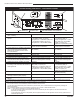
Stardance Direct Vent/Natural Vent Gas Heater Wiring Diagrams ON OFF FAN POWER CORD Thermopile Black On/Off Switch Wiring TP/TH Millivolt Gas Valve TP Chassis Ground Black TH Thermostat Black BL Thermostat (Optional) (Optional) Optional Thermostat Wiring TP K GRN ST124b K BLK FAN JUNCTION BOX St124b on/off/switch wiring 1/11/00 djt Thermopile TP/TH BLK WHT BL Strain Relief Millivolt Gas Valve ON / OFF Rheostat Black TH ST124c Fig.
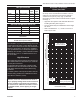
Stardance Direct Vent/Natural Vent Gas Heater 2 6 5 4 T EN EM 7 C 1a 3 11 12 1c 13 14 10a 1b 18 15 T OFF 8a,b 16 17 O H PILOT ADJ ON L I LO PI 19 10b 9a,b PIL OT 10c OFF • D REMOTE 22 LE 20 LOCAL ON • 21 23 28 29 25a,b, c,d 27 32 31 30 24 35 34 38 40 39 36 26 41 48a,b 33 42 49 7065 CFM Corporation reserves the right to make changes in design, materials, specifications, prices and discontinue colors and products at any time, Stardance without notice
Stardance Direct Vent/Natural Vent Gas Heater Stardance Direct Vent/Natural Vent Gas Heater (SDV30) Models 3900-3916, 3940-3956 (continued) Ref. 2. 3. 4. 5. 6. 7. 8a. 8b. 9a. 9b. 10a. 11. Description Gasket Cement Manifold Assembly Lava Rocks Burner Gasket, Glass - Med.
Stardance Direct Vent/Natural Vent Gas Heater Stardance Direct Vent/Natural Vent Gas Heater (SDV30) Models 3900-3916, 3940-3956 (continued) Ref. Description 34. 35. 36. 37. 38. 39. 40. 41. 42. 43. 44. 45. 46. 47. 48a. 48b. 49. 50.
Stardance Direct Vent/Natural Vent Gas Heater Optional Accessories Fan Kits FK26 Fan The FK26 fan helps distribute heated air from within the firebox out into the room. The fan is controlled by a snapstat that turns power on and off as the firebox temperature rises above and falls below a preset temperature. A rheostat provides for variable fan speeds. Specifications 115 Volt / 60Hz / .
Stardance Direct Vent/Natural Vent Gas Heater 40 20007065
Stardance Direct Vent/Natural Vent Gas Heater 20007065 41
Stardance Direct Vent/Natural Vent LIMITED Gas Heater LIFETIME WARRANTY PRODUCT COVERED BY THIS WARRANTY All Vermont Castings gas stoves, gas inserts, and gas fireplaces, and all Majestic brand gas fireplaces equipped with an Insta-Flame Ceramic Burner, or standard steel tube burner.
GARANTIE À VIE LIMITÉE Stardance Direct Vent/Natural Vent Gas Heater PRODUIT COUVERT PAR LA PRÉSENTE GARANTIE L’ensemble des cuisinières à gaz, des poêles encastrables et des foyers à gaz Vermont Castings, ainsi que l’ensemble des foyers à gaz de marque Majestic équipés d’un brûleur en céramique Insta-Flame ou d’un brûleur en acier du fabricant, les réparations, les pièces et la main-d’œuvre seront standard.
Efficiency Ratings Model SDV30RN SDV30RP SDV30RFN SDV30RFP EnerGuide Ratings Fireplace Efficiency (%) 63.0 63.0 63.0 63.0 CFM Corporation 410 Admiral Blvd. • Mississauga, Ontario, Canada L5T 2N6 800-668-5323 • www.cfmcorp.