
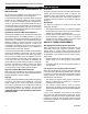
Operating instructions
ST128b
Stardance
flue centerline
9/28/00 djt
C
L
C
L
B
D
C
A
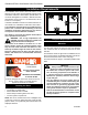
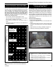
Parallel Installation: Minimum Clearance
and Flue Centerline, Direct Vent and
Natural Vent
ST128b
Stove Clearances: A: 4” (102 mm)
B: 4” (102 mm)
Pipe Centerlines: C: 15
1
⁄2” (395 mm)
D: 9” (229 mm)
Figure 3 Parallel installation, minimum back and side clear-
ances, and ue centerlines.
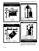
Corner Installation:
Minimum Clearance and Flue Centerline,
Direct Vent and Natural Vent
ST129b
Stardance
corner specs
9/28/00 djt
A
A
B
B
Stove Clearance: A: 4” (102 mm)
Pipe Centerline: B: 14
1
⁄2” (370 mm)
ST129b
Figure 4 Corner installation, minimum corner clearance and
ue centerline.
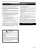
Wall Centerline from Floor
ST131b
Stardance
wall thimble
9/28/00 djt
A
Direct Vent Only
ST131b
Effective Minimum
Wall Thimble 56” (1480 mm)
(Vermont Castings Group Pipe)
Centerline 52” (1378 mm) (DuraVent Pipe)
Figure 5 Minimum wall thimble centerline.
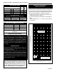
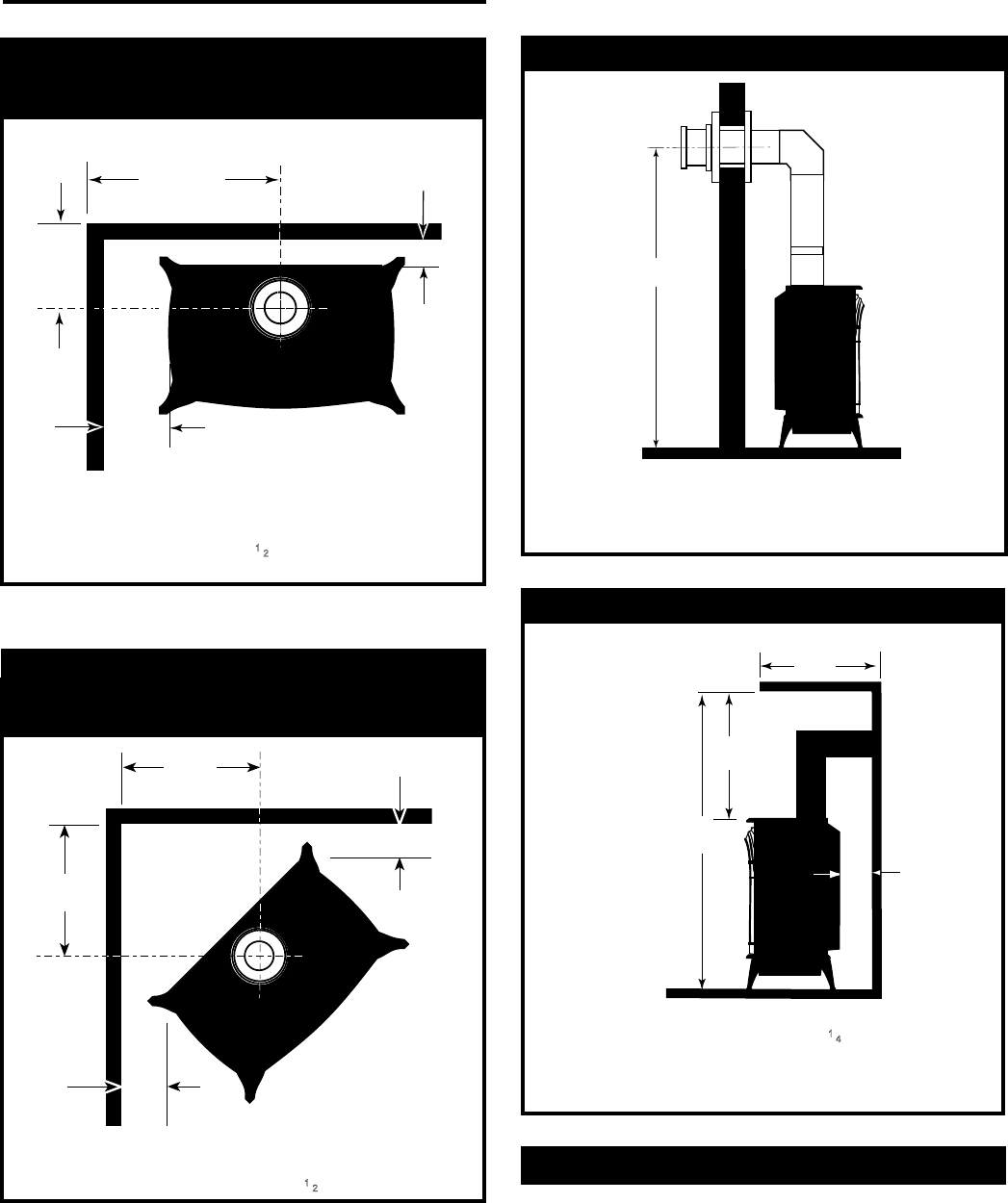
Wall and Ceiling Clearances
A
C
D
ST101b
Stardance
Direct Vent
Min. Clrnc
9/28/00 djt
B
ST101b
A: Rear Wall 4” (102 mm)
B: Min. Clearance 45
1
⁄4” (1154 mm)*
C: Min. Alcove Height 72” (1830 mm)
D: Max. Alcove Depth 48” (1220 mm)
Sidewall Clearance 4” (102 mm)
Figure 6 Dimensions and clearances to ceiling or alcove.
Hearth Requirements
The Stardance Heater must be installed on rigid ooring.
When the heater is installed directly on any combustible
surface other than wood ooring, a metal or wood panel
extending the full width and depth of the unit must be
used as the hearth. There are no other hearth require-
ments.
7
Stardance® Direct Vent/Natural Vent Gas Heater
20306760