
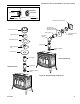
Operating instructions


interference with wall studs, electrical wiring, conduit,
plumbing pipe or other obstructions. The termination
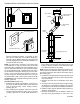
should be located at least 12” (305 mm) (Figure 39)
above grade, remain above the snow line in geographi-
cal areas that accumulate snow and be away from trafc
areas such as walkways if it is less than 7’ (2.1 m) high.
Refer to Pages 11, 12, Figures 11, 12 for more detail.
2. Assemble the pipe (and elbow if using) and attach it to
the appliance. Plan for a level to 1/4” per foot rise (6
ST928
Selkirk firestop
6/07
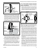
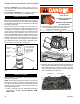
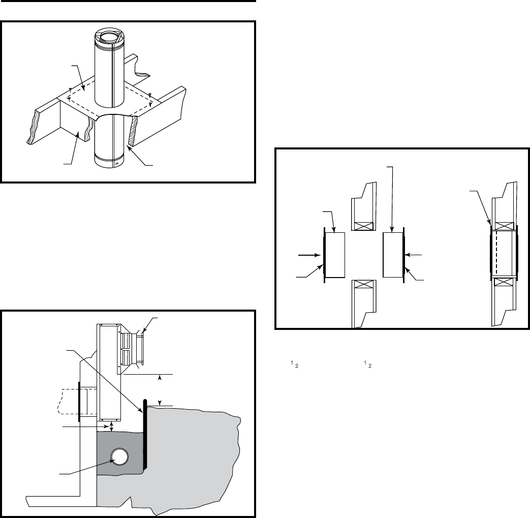
Firestop (FS)
Placed on Top
of Framed
Opening
Attic Framing
(No oor)
Maintain at Least
Minimum Clearance to
Combustibles, Wire and
Insulation
ST928
Figure 38 Firestop spacer.
quire it. Contact the appliance manufacturer for information
if uncertain. When installed in Canada, a wall thimble is
required on all installations in which the vent passes
through a combustible wall.
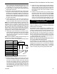
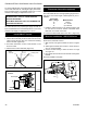
5. If required, install the outside half of the wall thimble (WT)
through the opening and screw or nail in place. (Figure
40) Seal around the perimeter of the thimble face plate on
the exterior wall using an RTV silicone sealant to provide
protection from possible rain inltration. (Figure 40)
ST929
Slkrk snorkel
6/07
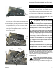
Snorkel Termination
Window Well
12” (305 mm) Minimum
Clearance Above Grade Level to
Air Intake
Grade Level
Sloped Away
From Building
Adequate
Drainage as per
Local Codes
Maintain 2”
(51 mm)
Clearance
Below Snorkel
ST929
Figure 39 Below grade installation.
ST930
Selkirk wall thimble
6/07
Wall
Thimble
Shield
Seal with RTV
Silicone Sealant
on Exterior side
here (around
perimeter)
Wall Thimble
Shield
Wall
Thimble
Face
Plate
Wall Thimble
Face Plate
ST930
Figure 40 Wall thimble.
mm per 305 mm) (from inlet to outlet) in the horizontal
system if not specied by the appliance manufacturer.
Horizontal runs should be supported every 4’ (122 cm).
3.
Push the appliance near the desired location. Determine
the centerpoint of the penetration by locating the center-
line of the outlet of the pipe with respect to the wall.
4. Frame an opening to the dimension specied in the
Framing Dimension Table 1. Ensure the centerline of
the pipe lines up with the center of the prepared open-
ing unless otherwise specied by the appliance manu-
facturer.
NOTE: As a general rule, the wall thimble is optional in the
U.S. However, there may be some manufacturers that re-
NOTE: The wall thimble accommodates wall thicknesses
of 4
1
⁄2” (114 mm) to 7
1
⁄2” (191 mm). If a larger range is need-
ed due to a thicker wall, it is permissible to eld fabricate a
metal sleeve extension and attach it to the shields.
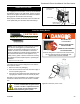
6. Install the horizontal termination to the exterior wall us-
ing four (4) all purpose screws through the holes located
at each corner of the termination. Make sure the arrow
(embossed on the front of the termination) is pointing
up. (Figure 41) If the house has vinyl siding, a Vinyl
Siding Standoff (VS) must be installed prior to installing
the horizontal termination. Refer to the appliance man-
ufacturer to determine if one is recommended. Attach
the vinyl siding standoff to the exterior side of the wall
(making sure it is level and centered with respect to the
opening) with screws (provided) at each corner of the
standoff. Attach the horizontal termination to the stand-
off. (Figure 42)
If the wall is brick or concrete, and contains no combus-
tible material, a 7” (178 mm) round penetration hole is
adequate. The wall thimble is not required. The perforat-
ed straps of the horizontal termination provide a method
of attachment. These can either be threaded through
the opening or wall thimble (if used) and screwed to the
pipe or removed with a pair of tin snips if not used. Use
proper masonry fasteners to attach the horizontal termi-
nation to the wall.
7. If a wall thimble is used, push the pipe (which is connect-
ed to the appliance) carefully through the wall thimble
until the DIRECT-TEMP pipe becomes fully engaged
23
Stardance® Direct Vent/Natural Vent Gas Heater
20306760