
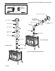
Operating instructions


Supporting DIRECT-TEMP: Vertical Support
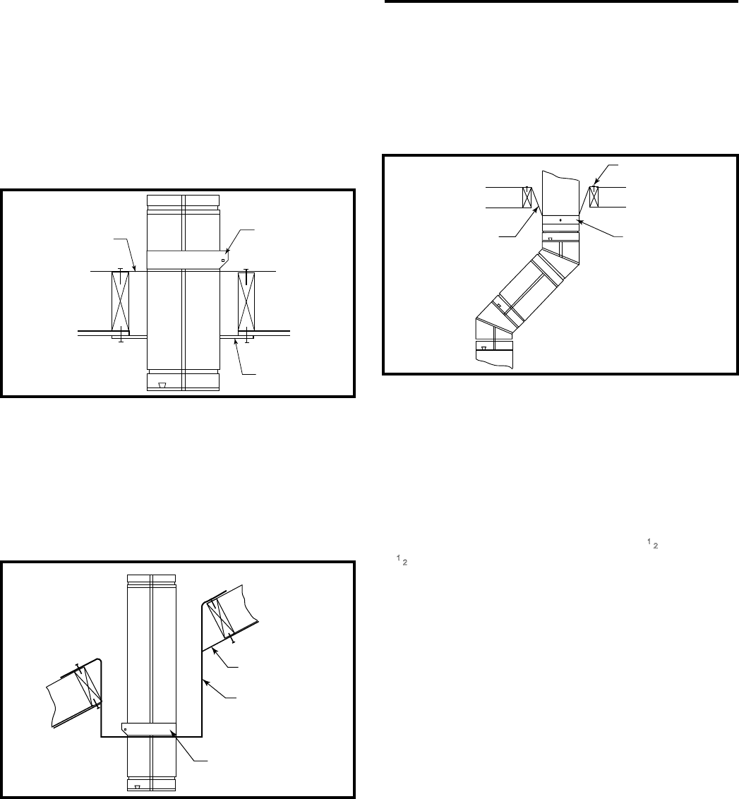
Vertical installations can be supported by two methods:
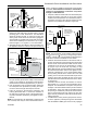
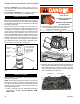
Ceiling Support (CS) (used in at ceiling installation) comes
with a support plate and a support collar. Install it by screw-
ing the support plate to the top of the properly framed ceil-
ing joist opening, using screws provided. A round trim plate
(TP) is attached to the ceiling, using screws, to provide a
nished appearance once installed. (Figure 35)
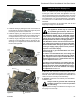
The Cathedral Ceiling Support (CCS) may be used in
ST923
Selkirk
vertical support
6/07
Ceiling Support
Plate
Ceiling Support
Collar
Trim Plate
ST923
Figure 35 Ceiling support.
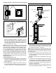
pitched or at ceiling installations and comes with a sup-
port collar and a decorative two part square trim plate. In-
stall by inserting the support box down through the framed
joist opening (end with round hole rst) in the ceiling using
tin snips, cut the corners of the open end of the box such
that the sides can be folded down over the top of the joist
framing members. Nail the folded sides to the top of the
framing. (Figure 36)
ST926
Selkirk Support Box
6/07
Two Part Square
Trim Plate
Support Box
Support Box Collar
ST926
Figure 36 Support box.
A two-part square trim plate is provided to give a nished
look once installed. Simply t the two halves of the trim
plate around the cathedral ceiling support box hanging be-
low the ceiling (overlapping if necessary) and screw them
to the ceiling. Both the ceiling support and cathedral ceiling
support can support a maximum of 40’ (12 m) of pipe.
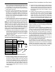
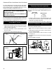
Offsets:
If any offsets are necessary in the vertical system, an Off-
set Support (OS) should be installed directly above the
upper elbow of the offset. Install by attaching the offset
support band to the pipe with two #8 x 1/4” sheet metal
screws (minimum ) and secure the offset support straps to
surrounding structure. (Figure 37)
KT927
slkrk offset support
6/07
Nail to top of
framing
Offset Support
Strap
Offset Support
Collar
ST927
Figure 37 Offset support.
Supporting DIRECT-TEMP: Horizontal Support
Horizontal runs of Direct-Temp should be supported every
4’ (122 cm) of pipe. This can be done with the use of plumb-
ers strapping or the offset support.
Adjustable Length (AJ)
An Adjustable Length is available to accommodate instal-
lations where non-standard lengths are necessary. The ad-
justable length telescopes down over a standard length of
pipe and provides an extension range of 3
1
⁄2” (89 mm) to
10
1
⁄2” (267 mm). Install by sliding the inlet end of the ad-
justable length over the outlet end of a standard length of
pipe. After positioning the adjustable length appropriately,
secure it to the standard length with two (2) #8 x1/4” sheet
metal screws (provided). Seal the area between both the
top and bottom of the adjustable length outer wall and the
outer wall of the standard length with an approved silicone
sealant.
Fire Stopping
DIRECT-TEMP must be restopped wherever it passes
through oors, ceiling or walls. The only location where a
restop is not required is at the roof level. Both vertical sup-
port components with trim plates provide for restopping.
The wall thimble also acts as a restop. at other locations,
a restop spacer (FS) should be installed. In the attic the
restop should be placed on top of the joist framing to pre-
vent debris from falling into the joist framing. (Figure 38)
Horizontal Installation
1. Determine the appliance location. Refer to the appliance
manufacturer’s installation instructions for clearance to
combustible requirements, termination options, num-
ber of elbows, maximum length, etc. Then position the
appliance and plan vent routing accordingly. Consider
locating the appliance in a place where there will be no
22
Stardance® Direct Vent/Natural Vent Gas Heater
20306760