
Operating instructions


ST222
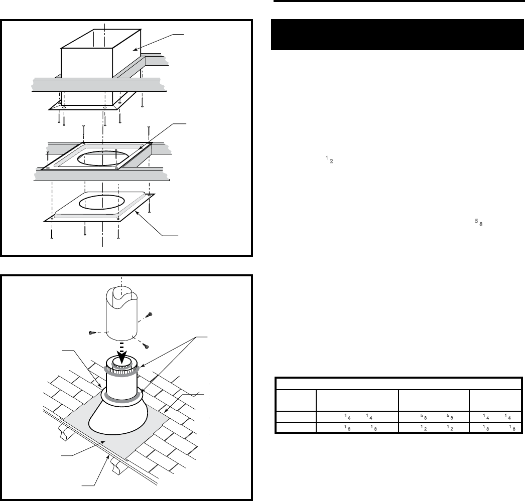
vent thru ceiling
12/99
#7DVAIS
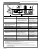
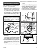
Attic Insulation
Shield
#7DVFS
Firestop in
Upper Floor
#7DVFS
Firestop in
Ceiling
Use Four
8dNails
ST222
Figure 31 Install restops and attic insulation shield.
ST221
vent thru roof
12/99
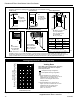
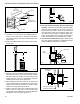
Sealant
Storm Collar
Use three #5 sheet
metal screws at
each joint
Upper edge
of ange
goes under
upper
shingles
Flashing
#7DVSKV
(A, B, or F)
RoofSupport
ST221
Figure 32 Roof support and ashing.
Selkirk Direct-Temp Metalbestos Direct Vent
System
Installation Instructions
1. Determine whether the length of pipe ts the appliance
outlet by attempting to engage the parts. If the parts en-
gage smoothly, proceed to Step 2. If obstructions, inter-
ference or loose t is noted, contact the appliance man-
ufacturer or Selkirk Metalbestos with the dimensions of
the appliance outlet.
2. Slide the length of pipe over the appliance outlet a mini-
mum of 1
1
⁄2” and screw to the appliance outlet collar us-
ing a minimum of two (2) #8 x 1/4” sheet metal screws.
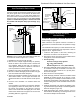
Appliance Adapter (AAV)
The appliance adapter (AAV) adapts DIRECT-TEMP to
most direct vent appliances incorporating outlet collars
congured to receive most common 4” (ID) 6
5
⁄8” (OD) or
5” (ID) by 8” (OD) “Twist Lock” Style, direct vent systems.
The adapter incorporates two (2) indentations on the outer
wall of the inlet end, which are designed to “Twist Lock”
into place upon attachment to the appliance outlet. Align
the adapter indentations with the entry slots of the appli-
ance outlet and slide together. Turn the adapter clockwise
approximately one-quarter turn to lock in place. The outlet
end of the adapter is standard DIRECT-TEMP construction.
Use of Sealant
It is not required to apply or use sealant on the inner liner of
DIRECT-TEMP. For outer wall joint sealing considerations,
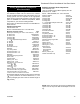
Framing Dimension Table 1
Model DT Ceiling Support (CS) Cathedral Ceiling Wall Thimble
Diameter Firestop (FS) Support CCS) (WT)
4” 8
1
⁄4” x 8
1
⁄4” 10
5
⁄8” x 10
5
⁄8” 8
1
⁄4” x 8
1
⁄4”
5” 10
1
⁄8” x 10
1
⁄8” 14
1
⁄2” x 14
1
⁄2” 10
1
⁄8” x 10
1
⁄8”
9. Install the storm collar and seal around the joints. (Fig-
ure 32)
10. Add additional vent lengths to achieve the proper
overall height.
11. Apply cement to the inner and outer termination col-
lars and install the terminal cap.
follow appliance manufacturer recommendations.
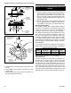
Joint Connection:
The pipe and elbows are assembled by inserting the out-
let (male) end of a length of pipe or elbow into the inlet
(female) end of an adjacent length of pipe or elbow. Make
sure the outlet end is fully seated within the inlet end of
the adjoining section and the gasket, located on the inner
liner of the inlet section is fully enclosed by the inner liner
of the outlet of the adjoining section. Push in the Lock Tab
such that it becomes seated within the inward groove of the
adjoining section. This locks the joint in place. (Figure 33)
20
Stardance® Direct Vent/Natural Vent Gas Heater
20306760