INSTALLER/ CONSUMER SAFETY INFORMATION PLEASE READ THIS MANUAL BEFORE INSTALLING AND USING APPLIANCE WARNING! IF THE INFORMATION IN THIS MANUAL IS NOT FOLLOWED EXACTLY, A FIRE OR EXPLOSION MAY RESULT CAUSING PROPERTY DAMAGE, PERSONAL INJURY OR LOSS OF LIFE. FOR YOUR SAFETY Installation and service must be performed by a qualified installer, service agency or the gas supplier.
RFSDV22/32/42 Freestanding Direct Vent Fireplace Table of Contents PLEASE READ THE INSTALLATION & OPERATING INSTRUCTIONS BEFORE USING APPLIANCE. Thank you and congratulations on your purchase of a CFM Specialty Home Products fireplace IMPORTANT: Read all instructions and warnings carefully before starting installation. Failure to follow these instructions may result in a possible fire hazard and will void the warranty. Installation Instructions Important Curing/Burn Information ............................
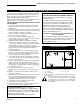
RFSDV22/32/42 Freestanding Direct Vent Fireplace Installation and Operating Instructions This gas fireplace should be installed by a qualified installer in accordance with local building codes and with current CSAB149.1 Installation codes for Gas Burning Fireplaces and Equipment and CAN/CSA Z 240.4 Canada. FOR U.S.A Installations follow local codes and/or the current National Fuel Gas Code. ANSI Z223.1/NFPA 54. FOR SAFE INSTALLATION AND OPERATION PLEASE NOTE THE FOLLOWING: 1 .
RFSDV22/32/42 Freestanding Direct Vent Fireplace Fireplace Dimensions A K C G DE I J F B A H RFSDV22 K C DE G I J F B A H RFSDV32 K D M L C I N J RFSDV42 B H Fig. 2 Fireplace specifications. Ref.
RFSDV22/32/42 Freestanding Direct Vent Fireplace High Elevations Clearance to Combustibles Adequate clearances as listed below must be maintained for servicing and proper operation: Back ............................................................... 0" (0mm) Side .......................................................... 12" (305mm) Floor ............................................................... 0" (0mm) Top ........................................................... 36" (914mm) Corner ............
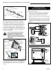
RFSDV22/32/42 Freestanding Direct Vent Fireplace Installation of Remote Switch for RN/RP Gas Valve 1/2" Gas Supply 1/2" x 3/8" Reducer Install on/off switch assembly on either the rear right or left side of the Fireplace. 3/8" Nipple 3/8" Nipple 3/8" x 3/8" Shut Off Valve 3/8" Union 3/8" Nipple CFM106 Fig. 3 Typical gas line installation. Thermopile TP TH The fireplace valve must not be subjected to any test pressures exceeding 1/2 psi.
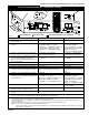
RFSDV22/32/42 Freestanding Direct Vent Fireplace General Venting Information - Termination Location INSIDE CORNER DETAIL G V H A D V N N E V B C V L B Fixed Closed Ope F B V Operable rab V le V Fixed Closed G V B B B V J X I A V VENT TERMINATION M G V K X V A X AIR SUPPLY INLET AREA WHERE TERMINAL IS NOT PERMITTED CFM145a Canadian Installations1 A = Clearance above grade, veranda, porch, deck, or balcony B = Clearance to window or door that may be opened C = Clearanc
RFSDV22/32/42 Freestanding Direct Vent Fireplace Termination Clearances Termination clearances for buildings with combustible and noncombustible exteriors. Inside Corner Recessed Location Outside Corner A= Combustible 6"(152mm) Noncombustible 2"(50mm) A V D B= Combustible 6"(152mm) Noncombustible 2"(50mm) V C C E V B Balcony with perpendicular side wall Balcony with no side wall C = Maximum depth of 48" (1219mm) for recessed location.
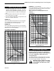
RFSDV22/32/42 Freestanding Direct Vent Fireplace How to Use the Vent Graph 1. Determine the height of the centre of the horizontal vent pipe exiting through the outer wall. Using this dimension on the Sidewall Vent Graph (Fig. 8 or 9), locate the point it intersects with the slanted graph line. 2. From the point of this intersection, draw a vertical line to the bottom of the graph. 3. Select the indicated dimension, and position the fireplace in accordance with same.
RFSDV22/32/42 Freestanding Direct Vent Fireplace When vent termination exits through foundations less than 20" (508mm) below siding outcrop, the vent pipe must flush up with the siding. A 7DVSS must also be used. It is always best to locate the fireplace in such a way that minimizes the number of offsets and horizontal vent length. 7.5 ft. 2286 mm The horizontal vent run refers to the total length of vent pipe from the flue collar of the fireplace to the face of the outer wall. A + B = 17 ft. (5.
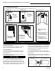
RFSDV22/32/42 Freestanding Direct Vent Fireplace Vertical Sidewall Installation Step 1 Locate the vent opening on the wall. It may be necessary to first position the fireplace and measure to obtain hole location. Depending on whether the wall is combustible or noncombustible, cut opening to correct size. (Fig. 14) For combustible walls, first frame in opening. Combustible Walls: Cut a 9³⁄₈" x 9³⁄₈" (240mm x 240mm) hole through the exterior wall and frame as shown. (Fig.
RFSDV22/32/42 Freestanding Direct Vent Fireplace Support horizontal pipes every 36" (914mm) with metal pipe straps. X Check fireplace to make sure it is levelled and properly positioned. FP1338 Fig. 18 Measure horizontal venting length plus 2". Step 6 NOTE: If using the charcoal wall plate, Part #52202CG, and collar, part #52203CG, put them in place before putting the pipe sections through the wall. Use appropriate length of pipe sections - telescopic or fixed - and install.
RFSDV22/32/42 Freestanding Direct Vent Fireplace Do Not Back Fill Around Snorkel. Soil Should Not Be Less Than 4" Below Snorkel. Maximum horizontal length - 45o elbows 10 ft. (3m) - 45o elbows 8.5 ft. (2.6m) - 45o elbows 7 ft. (2m) Snorkel Firestop 7" Pipe Example: 0 1 2 Screws 4" Clearance Maximum 10' (305cm) Ground Window Well Minimum 8' (2.4m) Maximum 40' (12.
RFSDV22/32/42 Freestanding Direct Vent Fireplace Typical Roof Support Application Typical Ceiling Support Application (7DVCS) FP1184 Fig. 25 Venting supports. 2' Min. 9. Install storm collar and seal around the pipe. 10. Add additional vent lengths for proper height. (Fig. 26) 11. Apply high temperature sealant to 4" and 7" collars of vertical vent termination and install.
RFSDV22/32/42 Freestanding Direct Vent Fireplace Twist Lock Venting Components Starter Kit -Model 7TDVSK - Sidewall Venting Starter Kit - Model 7TDVSKV - Vertical Venting for 7TDVSKV-A order 1/12 to 6/12 roof pitch for 7TDVSKV-B order 7/12 to 12/12 roof pitch for 7TDVSKV-F order flat roof Starter Kit - Model 7TDVSKS -Snorkel Kit for Below Grade Installation 45º elbow kit 7DVT45 for Vertical Installation Offsets 90º transition elbow kit 7TDVRT90 for Vertical Sidewall Applications or thru-the-roof.
RFSDV22/32/42 Freestanding Direct Vent Fireplace Operating Instructions Glass Information Trim Removal Only glass approved by CFM Specialty Home Products may be used for replacement. • The use of substitute glass will void all product • • • warranties. Care must be taken to avoid breakage of the glass. Under no circumstances should this fireplace be operated without the front glass or with a broken glass.
RFSDV22/32/42 Freestanding Direct Vent Fireplace RFSDV42 1 . Remove both Bay Window brass trims (See Trim Removal section). 2. Open the two clamps (Fig. 31) underneath the Bay Window that holds the Bay Window Frame and Glass Frame. 3. Lift and unhook the Bay Window assembly at the top. 4. Lift and unhook the Glass Frame at the top. 5. Place front left log (KR2) on top burner, left side. Use log's bottom holes to locate it into the left bracket log locator studs. 6.
RFSDV22/32/42 Freestanding Direct Vent Fireplace SR5 SR6 SR4 SR2 SR3 SR1 FP1349 Fig. 35 Bay window ceramic refractory. Burner Lava Rock Placement LG281 RFSDV42 ONLY 1. Remove bay window assembly and glass frame (see "Glass frame Removal" section). 2. Remove logs from the unit. Logs may be hot! 3. Remove refractory from packaging. Refractory are fragile and must be handled with care. Where at all possible, two hands should be used when handling. 4.
RFSDV22/32/42 Freestanding Direct Vent Fireplace Flame Characteristics It is important to periodically perform a visual check of the pilot and the burner flames. Compare them to the Figures 39, 40 and 41. If any of the flames appear abnormal call a service person. 3/8" - 1/2" LG282 Fig. 40 Correct burner flame appearance for RFSDV22 and RFSDV32. SIT Pilot F584-703 PSE Pilot Fig. 39 Correct pilot flame appearance. LG283 Fig. 41 Correct burner flame appearance for RFSDV42.
RFSDV22/32/42 Freestanding Direct Vent Fireplace Lighting And Operating Instructions FOR YOUR SAFETY READ BEFORE LIGHTING WARNING:If you do not follow these instructions exactly, a fire or explosion may result causing property damage, personal injury or loss of life. A. This heater has a pilot which must be lit manually. When lighting the pilot follow these instructions exactly. B. BEFORE LIGHTING smell all around the heater area for gas.
RFSDV22/32/42 Freestanding Direct Vent Fireplace Troubleshooting the Gas Control System SIT 630 Gas Valve NOTE: Before trouble shooting the gas control system, be sure external gas shut off is in the "On" position. WARNING: Before doing any gas control service work, remove glass front. Symptom Possible Causes Corrective Action 1. Spark ignitor will not light A. Defective or misaligned electrode at pilot. Using a match, light pilot. If pilot lights, turn off pilot and push the red button again.
RFSDV22/32/42 Freestanding Direct Vent Fireplace Troubleshooting the Gas Control System Honeywell Millivolt Valve START CHECK Gas Supply On NO Supply Line Hooked Up Shutoff Valve Open YES Pilot Lights With Piezo Ignitor NO YES Pilot Stays Lit NO Lockout Has Engaged. Wait 60 Seconds And Try Again. For Spark At Electrode While Depressing Piezo 1/8" Gap To Pilot Hood Needed. All Wiring Connections Replace Piezo Ignitor For Air In The Lines Thermopile Needs A Minimum 325mv.
RFSDV22/32/42 Freestanding Direct Vent Fireplace Troubleshooting the Gas Control System SIT NOVA 820 Millivolt Valve NOTE: Before trouble shooting the gas control system, be sure external gas shut off is in the “On” position. WARNING: Before doing any gas control service work, remove glass front. SYMPTOM 1. Spark ignitor will not light 2. Pilot will not stay lit after carefully following lighting instructions. 3. Pilot burning, no gas to main burner 4. Frequent pilot outage problem.
RFSDV22/32/42 Freestanding Direct Vent Fireplace Maintenance Burner and Burner Compartment It is important to keep the burner and the burner compartment clean. At least once per year the logs and lava rock/ember material should be removed and the burner compartment vacuumed and wiped out. Remove and replace the logs as per the instructions in this manual. Always handle the logs with care as they are fragile and may also be hot if the fireplace has been in use.
RFSDV22/32/42 Freestanding Direct Vent Fireplace 9 a/b 41 4 43 42 34 35 3a/b 38 43 43 10 26 44 11 18 17 15 32 33 39 31 19 29 33 23 22 36 a/b 5/6 a,b 13 47 21a,b 8 a/b 7 a/b LO 30 PIL 37 it OT OFF HI 39 28 25a,b 16 17 T LO PI O H PILOT ADJ ON I L 40 12 10a/b OFF 24a,b 39 46 2 20 45 41 13 27 42 1d 1d 43 1f 1f 1e 1e 1c 1b 1b 1c 1a 1a 1028 CFM Specialty Home Products reserves the right to make changes in design, materials, specifications, prices and d
RFSDV22/32/42 Freestanding Direct Vent Fireplace RFSDV22/32/42 Series (continued) Ref.Description 1. 1a. 1b. 1c. 1d. 1e. 1f. 2. 3a. 3b. 4. 5a. 5b. 6a. 6b. 7a. 7b. 8a. 8b. 9a. 9b. 10a. 10b. 11. 12. 13. 14. 15. 16. 17. 18. 19. 20. 21a. 21b. 22. 23 24a. 24b. 25a. 25b. 26. 27. 28. 29. 30. 31. 32. 33. 34. 35. 36a. 26 Log Set Complete Log Ember Front Log Front Left Log Front Right Log Rear Log Top Left Log Top Right Burner Lava Rock (Package) Burner with Tiles Nat. Burner with Tiles Prop.
RFSDV22/32/42 Freestanding Direct Vent Fireplace RFSDV22/32/42 Series (continued) Ref. Description 36b. 37. 38. 39. 40. 41. 42. 43. 44. 45. 46. 47. 48. 49. Frame Window - Right Side Frame Window - Front Bay Window Assy.
RFSDV22/32/42 Freestanding Direct Vent Fireplace Accessories Fan Kits Stud FK24 Standard on RFSDV42 It will be easier to install the fan before connecting the gas line to the fireplace. 1. Open front access door panel by pulling forward on brass lip. 2. Install the fan through the opening at the back of the pedestal, with the outlet pointed up and the fan mounting bracket facing the back of the fireplace. (Fig. 43) The fan mounts over two studs which hold the fan just below the firebox floor.
RFSDV22/32/42 Freestanding Direct Vent Fireplace For Use in Mobile Homes - Model RFSDV32RMH This appliance may be installed as an OEM installation in a manufactured (mobile) home and must be installed in accordance with the manufacturer's instrucitons and the manufactured home construction and safety standard, Title 24 CFR, Part 3280 or Standard for Installation in Mobile Homes, CAN/CSA Z240 MH. This appliance is only for use with the type(s) of gas indicated on the rating plate.
RFSDV22/32/42 Freestanding Direct Vent Fireplace LIMITED LIFETIME WARRANTY PRODUCT COVERED BY THIS WARRANTY All Vermont Castings gas stoves, gas inserts, and gas fireplaces, and all Majestic or Northern Flame brand gas fireplaces equipped with an Insta-Flame Ceramic Burner, or standard steel tube burner.