Freestanding Direct Vent Gas Stove with the LexFire Burn System™ Model: RFSDV34 INSTALLER/CONSUMER SAFETY INFORMATION PLEASE READ THIS MANUAL BEFORE INSTALLING AND USING APPLIANCE WARNING! IF THE INFORMATION IN THIS MANUAL IS NOT FOLLOWED EXACTLY, A FIRE OR E X P L O S I O N M AY R E S U LT CAUSING PROPERTY DAMAGE, PERSONAL INJURY OR LOSS OF LIFE. FOR YOUR SAFETY Installation and service must be performed by a qualified installer, service agency or the gas supplier.
RFSDV34 Freestanding Direct Vent Gas Stove Table of Contents PLEASE READ THE INSTALLATION & OPERATING INSTRUCTIONS BEFORE USING THIS APPLIANCE. Thank you and congratulations on your purchase of an Vermont Castings Group gas stove. IMPORTANT: Read all instructions and warnings carefully before starting installation. Failure to follow these instructions may result in a possible fire hazard and will void the warranty. Installation & Operating Instructions General Information, Warnings, Cautions...............
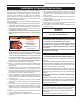
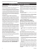
RFSDV34 Freestanding Direct Vent Gas Stove Installation & Operating Instructions This gas stove should be installed by a qualified installer in accordance with local building codes and with current CSA-B149.1 Installation codes for Gas Burning Appliances and Equipment. If the unit is being installed in a mobile home, the installation should comply with the current CAN/USA Z240.4 code. For USA Installations follow local codes and/or the current National Fuel Gas Code. ANSI Z223.1/NFPA 54.
RFSDV34 Freestanding Direct Vent Gas Stove Installation & Operating Instructions Requirements for the Commonwealth of Massachusetts All gas fitting and installation of this heater shall only be done by a licensed gas fitter or licensed plumber.
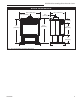
RFSDV34 Freestanding Direct Vent Gas Stove Stove Dimensions 2656M” (667 mm) 1356 ” (333 mm) 1956O” (495 mm) 6 6 ” (162 mm) 456O” (114 mm) 3156O” (800 mm) 30” (762 mm) 1556O” (394 mm) 10” (254 mm) 2656M” (667 mm) 19 6 ” (492 mm) Fig. 1 Stove specifications and framing dimensions.
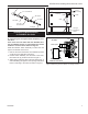
RFSDV34 Freestanding Direct Vent Gas Stove Gas Specifications Locating Your Stove 12” (305 mm) A D B 12” (305 mm) Model Fuel Gas Control RFSDV34TSRN Nat Millivolt Hi/Lo RFSDV34TSRP Prop Millivolt Hi/Lo C Preparation E FP1620 Fig. 2 Locate gas stove. A) Flat on wall* D) Cross Corner B) Room Divider* FP1620 E) Flatlocate on wall corner freestanding C) Island Note (Fig. 2): *(A) and (B) must maintain a 12” (305 mm) clearance between the wall and side glass of stove.
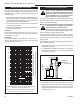
RFSDV34 Freestanding Direct Vent Gas Stove 1/2” Gas Supply 1/2” x 3/8” Reducer Screw (through existing hole) Screw ON/OFF Switch Assembly 3/8” Nipple Clips 3/8” Union 3/8” Nipple 3/8” x 3/8” Shut-Off Valve CFM106 3/8” Nipple Wiring for Millivolt Gas Valves Fig. 3 Typical gas line connection. Installation of Remote Switch CFM106 for RSN/RSP Valve Typical Gas LineGas Connection NOTES: The 9-29-00 remote ON/OFF switch cannot be fitted to units using the Honeywell Radio Frequency control valve.
RFSDV34 Freestanding Direct Vent Gas Stove General Venting Information - Termination Location INSIDE CORNER DETAIL V G N H A D L V E C B V F B Fixed Closed Ope V B CFM145a V VENT TERMINATION B V Operable rable B V V Fixed Closed J X B A X AIR SUPPLY INLET M I V K X AREA WHERE TERMINAL IS NOT PERMITTED Canadian Installations1 US Installations2 CFM145a A = Clearance above grade, veranda, porch, 12” (30cm) 12” (30cm) DV Termin Location deck, or balcony 5/01/01 Rev.
RFSDV34 Freestanding Direct Vent Gas Stove Termination Clearances Termination clearances for buildings with combustible and noncombustible exteriors. Alcove Applications* Inside Corner Outside Corner G= Combustible 6" (152 mm) G Noncombustible 2" (51 mm) V F= Combustible 6" (152 mm) Noncombustible 2" (51 mm) V C V O F Balcony with perpendicular side wall Balcony with no side wall D C E E = Min. 2” (51 mm) for non-vinyl sidewalls Min. 12” (305 mm) for vinyl sidewalls O = 8’ (2.4 m) Min.
RFSDV34 Freestanding Direct Vent Gas Stove How to Use the Vent Graph Vertical Sidewall Applications The vent chart should be read in conjunction with the following vent installation instructions to determine the relationship of the vertical and horizontal dimensions of the vent system. 1. Determine the height of the center of the horizontal vent pipe exiting through the outer wall. Using this dimension on the Sidewall Vent Graph (Fig. 8), locate the point intersecting with the slanted graph line. 2.
RFSDV34 Freestanding Direct Vent Gas Stove Example: Elbow 1 Elbow 2 Elbow 3 Elbow 4 Total angular variation = 90° = 45° = 45° = 90° = 270° 7.5ʼ (2286 mm) 1 + 2 + 3 + 4 = 270° A + B =17’ (5.2 m) Max. FP1496 Fig. 10 90° elbow used in horizontal vent run. FSDV 2 elbow 20 appl. 20ʼ (6 m) rev 0602 rjs 7.5ʼ (2. m) FP1239 Fig. 12 Maximum elbow usage.
RFSDV34 Freestanding Direct Vent Gas Stove STEP 2 Measure wall thickness and cut zero clearance sleeve parts to proper length (MAXIMUM 12”/305 mm). Assemble sleeve and attach to firestop with #8 sheet metal screws (supplied). Install firestop assembly. (Fig. 14) Zero clearance sleeve is only required for combustible walls. Bead of Sealant Max. Length 12” (305 mm) Adjustable Zero Clearance Sleeve #8 Screws (2) #8 Screws (2) #8 Screws (2) Firestop Adjustable Zero Clearance Sleeve FP1509 Fig.
RFSDV34 Freestanding Direct Vent Gas Stove Below Grade Installations When it is not possible to meet the required vent terminal clearances of 12” (305 mm) above grade level a snorkel vent kit is recommended. It allows installation depth of down to 7” (178 mm) below grade level. The 7” is measured from the center of the horizontal vent pipe as it penetrates through the wall. If venting system is installed below ground, we recommend a window well with adequate and proper drainage.
RFSDV34 Freestanding Direct Vent Gas Stove Do not back fill around snorkel. A clearance of at least 4” (102 mm) must be maintained between snorkel and the soil. Max. 8’ (2.4 m) If the foundation is recessed, use recess brackets (not supplied) for securing lower portion of the snorkel. Fasten brackets to wall first, then secure to snorkel with self drilling #8 x 1/2 sheet metal screws. It will be necessary to extend vent pipes out as far as protruding wall face. (Fig.
RFSDV34 Freestanding Direct Vent Gas Stove Vertical Through-the-Roof Installation 1. Locate your stove. 2. Plumb to center of the 4” (102 mm) flue collar from ceiling above and mark position. 3. Cut opening equal to 9³⁄₈” x 9³⁄₈” (240 x 240 mm). 4. Proceed to plumb for additional openings through the roof. In all cases, the opening must provide a minimum of 1” (25 mm) clearance to the vent pipe, i.e., the hole must be at least 9³⁄₈” x 9³⁄₈” (240 x 240 mm). 5. Place stove into position. 6.
RFSDV34 Freestanding Direct Vent Gas Stove Venting Requirements and Options Approved Vent System Components The heater must be vented to the outdoors through an adjacent exterior wall or through the roof. The venting system must be comprised of the appropriate listed venting components specified on this page. These parts are available from Selkirk Corporation, DuraVent Corporation or your Vermont Castings Group Dealer.
RFSDV34 Freestanding Direct Vent Gas Stove Operating Instructions Glass Information Glass Cleaning Only glass approved by Vermont Castings Group may be used for replacement. The use of substitute glass will void all product warranties. It is necessary to periodically clean the glass. During startup condensation, which is normal, forms on the inside of the glass. This condensation causes lint, dust and other airborne particles to cling to the glass surface. Take care to avoid breaking the glass.
RFSDV34 Freestanding Direct Vent Gas Stove Log Set and Lava Rock Material Installation Figure 27 1. Remove window frame assembly. (Refer to Window Frame Assembly Removal section) 2. Remove logs from packaging. As with all plastic items - these logs and their packaging are not toys and should be kept away from children and infants. 3.
RFSDV34 Freestanding Direct Vent Gas Stove Flame Characteristics Flame & Temperature Adjustment SRN/SRP Models LO Turn counterclockwise to increase flame height HI For units equipped with ‘HI/LO’ valves the flame adjustment is accomplished by rotating the ‘HI/LO’ adjustment knob located near the center of the gas control valve. (Fig. 28) It is important to periodically perform a visual check of the pilot and burner flames. Compare them to the pictorials illustrated below (Fig. 29-30).
RFSDV34 Freestanding Direct Vent Gas Stove Lighting and Operating Instructions FOR YOUR SAFETY READ BEFORE LIGHTING WARNING: If you do not follow these instructions exactly, a fire or explosion may result causing property damage, personal injury or loss of life. A. This heater has a pilot which must be lit manually. When lighting the pilot follow these instructions exactly. B. BEFORE LIGHTING smell all around the heater area for gas.
RFSDV34 Freestanding Direct Vent Gas Stove Troubleshooting the Gas Control System SIT NOVA 820 MILLIVOLT VALVE NOTE: Before trouble shooting the gas control system, be sure external gas shut off is in the “On” position. Symptom Possible Causes Corrective Action 1. Spark ignitor will not light A. Defective or misaligned electrode at pilot Using a match, light pilot. If pilot lights, turn off pilot and push the red button again.
RFSDV34 Freestanding Direct Vent Gas Stove Instructions for RCSITEA RFSDV34TSR Series CAUTION: The RCSITE is only certified for use on vented heater rated equipment. This remote control system provides a safe, reliable and user-friendly remote control for millivolt valve gas appliances, blower speed and flame height adjustment. The system can be manually or thermostatically turned on and off with the transmitter. Carefully inspect the contents for shipping damage.
RFSDV34 Freestanding Direct Vent Gas Stove The transmitter will operate the remote receiver from 1 foot to a maximum of 30 feet. The distance is reduce when batteries are low or when the receiver is inside a metal enclosure. Initial Startup Figure 34 °F 1. After initial power up or when RESET button is pressed, the transmitter is reset. The reset button is located behind the battery door of transmitter. FP2142 2. During system power up Fig.
RFSDV34 Freestanding Direct Vent Gas Stove Blower On Delay Time and OFF Delay Time Setting (Default 5 ON / 8 OFF) Figure 39 1. Hold FAN button for five (5) seconds and two (2) numbers will appear in the LCD screen. The upper one is ON Delay Time and the bottom is OFF Delay Time in minutes. 2. Use the ON / ▲ button to FP2146 set the desired On Delay Fig. 39 Blower time delay Time from 0 to 15 min- display. FP2146 utes. blower delay timer 3.
RFSDV34 Freestanding Direct Vent Gas Stove Testing Remote Control System 1. Light the gas appliance following the lighting instructions on Page xx. Confirm the pilot light is on; it must be in operation for the remote control to operate the main gas valve and blower. Appliance control knob must be in the ON position, and ON/OFF switch must be in OFF position. 2. Slide the 3 position button on the remote receiver to the ON position and the main gas flame should ignite. 3.
RFSDV34 Freestanding Direct Vent Gas Stove Troubleshooting Symptom 1. Battery icon on LCD on transmitter. 2. LCD display is blank. 3. LCD display shows “funny” display. 4. Appliance does not come on. 5. Receiver cannot receive signal. 6. Blower is not on after the stove is turned on. 26 Causes 1. Low battery. 1. Wiring/Electrical connections. 2. Privacy (DIP) switch setting on transmitter does not match receiver. 3. Transmitter measure temperature exceeding 99°F and shows “HI” on LCD. 4.
RFSDV34 Freestanding Direct Vent Gas Stove Burner and Burner Compartment Maintenance It is important to keep the burner and the burner compartment clean. At least once per year the logs and lava rock/ember material should be removed and the burner compartment vacuumed and wiped out. Remove and refit the logs as per the instructions in this manual. Always handle the logs with care as they are fragile and may also be hot if the stove has been in use.
RFSDV34 Freestanding Direct Vent Gas Stove Wiring Diagrams - RFSDV34TSR Black 120V AC Adapter Black mV Valve TH TP /TH Receiver 120V AC Plug Female Male SIT HI / LO Valve 120V AC Blower ST1091 Fig. 44 SIT Hi/Lo blower schematic. ST1090 120V AC Plug for Receiver SIT valve wiring SIT mV Valve Receiver Black Tag Tag Black Hi/Lo Regulator Tag: to blower Black Black White Tag: to 120V AC Black Blower White 120V AC Plug for Blower ST1092 Fig. 45 SIT Hi/Lo blower wiring.
RFSDV34 Freestanding Direct Vent Gas Stove 2 4 1e 27 1f 25 3 1d 1c 1b 21 1a 29 12 16 8 18 22 15 23 24 10 13 ON N FA 17 TO E AU AM FL F OF ON RS OF F 18 9a,b Vermont Castings Group reserves the right to make changes in design, materials, specifications, prices and discontinue colors and products at any time, without notice. RFSDV34 Ref. 1. 1a. 1b. 1c. 1d. 1e. 1f. 2. 3. 4.
RFSDV34 Freestanding Direct Vent Gas Stove RFSDV34 Ref. 5a. 5b. 5c. 5d. 6a. 6b. 7. 8a. 8b. 9a. 9b. 10. 11. 12. 13. 14. 15. 16a. 16b. 17. 18. 19. 20. 21. 22. 23. 24. 25. 26. 27. 28. 29. 30. 31. (continued) Description RFSDV34 Orifice, Main Burner - Nat. (not shown) Refer to Rating Plate Orifice, Main Burner - Prop. (not shown) Refer to Rating Plate Orifice, Front Burner - Nat.
RFSDV34 Freestanding Direct Vent Gas Stove Optional Accessories Fan Kits Refer to Page 28 for rewiring replacement components. FK24 Fan Assembly This auxiliary fan system increases the efficiency of the circulation of the heating air. The FK24 fan kit allows variable speed control of the circulation fan and also incorporates a heat sensor in the circuit.
RFSDV34 Freestanding Direct Vent Gas Stove Optional Brass Trim Kit Remote Control Options A decorative brass window trim kit, Model RFSDV34TKAP/ S is available for the RFSDV34 Freestanding Stove. These remote controls are available as an option only on stoves fitted with RN/RP gas control valves. Kit contents: Thermostatic Remote Control RCSITE, WWTD (1) Brass window trim (8) Magnets (3) Brass trim rings (for the vent pipe joints) Installation Procedure 1.
RFSDV34 Freestanding Direct Vent Gas Stove 10003550 33
RFSDV34 Freestanding Direct Vent Gas Stove 34 10003550
RFSDV34 Freestanding Direct Vent Gas Stove Limited lifetime warranty policy Lifetime Warranty The following components are warranted for life to the original owner, subject to proof of purchase: Firebox, Combustion Chamber, Heat Exchanger, Grate and Stainless Steel Burners. Five Year Warranty The following components are warranted five (5) years to the original owner, subject of proof of purchase: Ceramic Fiber Logs.
Based on CSA P.4.1-09 Efficiency Ratings Model RFSDV34TSRN RFSDV34TSRP EnerGuide Ratings Stove Efficiency (%) 72.1 72.1 D.O.E. (AFUE %) 70.0 70.0 Recherchez dans la brochure les caractéristique de rendement énergétique de foyer au gaz Énerguide Based CSA P.4.1-09 SelononCSA P.4.1-09 Vermont Castings Group 149 Cleveland Drive • Paris, Kentucky 40361 www.vermontcastingsgroup.