
Operating instructions

29
Radiance
®
Direct Vent Gas Heater
20306759
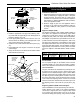
Install ON/OFF Switch - RADVT Series
The switch assembly parts are found in the parts bag.
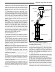
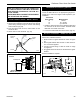
1. Attach switch assembly to left rear side of stove shroud
(when facing shroud) using two screws and existing
holes in shroud. (Fig. 52)
2. Run wires down back of stove, under bottom of rear
shroud to valve.
3. Attach wires to valve terminals. (Fig. 53)
THIS APPLIANCE SHOULD BE CONNECTED
TO THE GAS SUPPLY ONLY BY A QUALIFIED
GAS SERVICE TECHNICIAN. FOLLOW ALL
LOCAL CODES.
THERE MUST BE A GAS SHUT-OFF BETWEEN
THE STOVE AND THE SUPPLY.
ST315
attach switch assy
1/31/00 djt
Switch As-
sembly
Screws
Existing
Holes
ST315
Fig. 52 Attach switch assembly to rear shroud.
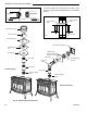
Thermostat Connection (optional)
Use only a thermostat rated for 500 - 750 millivolts.
Check the table below for the appropriate gauge ther-
mostat wire to use for the length of lead required in your
installation.
Thermostat
Wire / Gauge Maximum Run
18 20 feet
16 20 - 40 feet
14 up to 60 feet
1. Install the wall thermostat in the desired location and
run the wires to the stove location. Terminate these
leads with 1/4" female connectors.
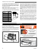
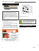
2. Connect the thermostat wires to the valve. (Fig. 53)
FP1622
Fig. 53 Install wiring to switch before connecting to valve.
P
I
L
O
T
TPTH
TP
TH
FP1622
SIT valve w/switch
SIt Valve
Valve
Thermopile
ON/OFF Switch or
Millivolt Thermostat
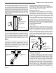
Receiver Installation - RADVTCS Series
Once the blower is installed to the back of the RADVTCS
Series stove, install the receiver.
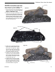
1. Slide receiver into igniter bracket as shown in Figure
54.
2. Attach igniter bracket with receiver to valve with #10-
32 x 1/4 screws supplied.
3. Connect receiver wiring to valve as shown on Page
44, Figure 91.
4. Plug igniter wire from burner into the back of the igniter
bracket.
Receiver installation complete.
ST1121
receiver install
Receiver
Igniter
Bracket
Valve
ST1121
Fig. 54 Install receiver.