
Operating instructions

2626
Radiance
®
Direct Vent Gas Heater
20306759
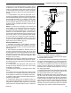
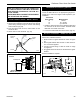
Minimum
Height
Above
Roof
ST934
minimum height
6/07
Minimum
Roof Pitch Height
Flat to 7/12 1’0"
Over 7/12 to 8/12 1’6"
Over 8/12 to 8/12 2’0"
Over 9/12 to 10/12 2’6"
Over 10/12 to 11/12 3’3"
Over 11/12 to 12/12 4’0"
Over 12/12 to 14/12 5’0"
Over 14/12 to 16/12 6’0"
Over 16/12 to 18/12 7’0"
Over 18/12 to 20/12 7’6"
Over 20/12 to 21/12 8’0"
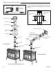
Fig. 45 Minimum Height Above Roof Requirements
11. Add lengths of pipe and restop as necessary until
assembly extends to a point above the roof which com-
plies with local code requirements for minimum termina-
tion height and with the appliance manufacturer’s installa-
tion instructions. (Fig. 45)
NOTE: Whenever DIRECT-TEMP penetrates through a
ceiling, a oor or a wall, it must be restopped.
12. Using a level, make sure the system is perfectly vertical.
13. Slide the ashing, suitable for the roof pitch, down
over the pipe protruding through the roof. Recheck ori-
entation and use a silicone sealant around and under the
perimeter of the ashing where it is in contact with the
roof. Secure the ashing with roong nails. Finish roof-
ing around the pipe, covering the sides and upper ares of
the ashing base with roong material. However, be sure
the lower unnailed portion of the base covers the roong
material.
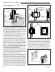
14. Position the storm collar around the pipe and slide
down until it is in contact with the ashing. Secure the
storm collar by inserting the two (2) tabs into the raised
slots and fold tabs back. Seal the area between the storm
collar and the vent pipe with a silicone sealant to prevent
rain inltration.
15. Install the vertical termination (VC) by inserting it
down into the top most section of pipe until it is fully seat-
ed. Depress lock tab to secure the cap to the pipe.
NOTE: In high wind areas, it is recommended to screw
termination to the pipe with two (2) #8 x 1/4" sheet metal
screws. The screws should be approximately 3/4" from
the bottom of the vertical termination’s galvanized collar.
ST139
Radiance
remove front
4/20/ 01 djt
ST139
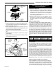
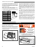
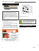
Fig. 46 Remove the safety barrier and stove front.
Install Log Set
Before beginning log installation, remove stove front and
glass frame. Refer to Figures 46 and 47.
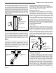
NOTE: Remove the safety barrier before you remove the
glass frame. To remove the barrier, simply lift up and pull
out until the tabs are clear of their corresponding slots on
the rebox. Then proceed to remove the glass frame by
following the steps below.
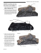
ST141
pull glass latch
10/99
ST141
Fig. 47 Release the latches to remove the glass frame.
DANGER
HOT GLASS WILL
CAUSE BURNS.
DO NOT TOUCH GLASS
UNTIL COOLED.
NEVER ALLOW CHILDREN
TO TOUCH GLASS.
Un panneau vitré chaud peut
causer des brûlures.
Laissez refroidir le panneau
vitré avant d’y toucher.
Ne laisser jamais les enfants
toucher le panneau vitré.
A barrier designed to reduce the risk of burns from
the hot viewing glass is provided with this
appliance and shall be installed.
Une barrière visant à réduire le risque de brûlure
par le hublot chaude est fournie avec cet
appareil et doit être installé.
DANGER