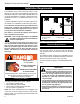
RADVT Series Radiance® Direct Vent Gas Heater Installation and Operating Instructions Models: RADVT(CS)CBSB, RADVT(CS)BSSB, RADVT(CS)BDSB, RADVT(CS)BMSB WARNING: FIRE OR EXPLOSION HAZARD Failure to follow safety warnings exactly could result in serious injury, death or property damage. • • • Do not store or use gasoline or other flammable vapors and liquids in the vicinity of this or any other appliance. WHAT TO DO IF YOU SMELL GAS – Do not try to light any appliance.
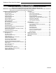
Radiance® Direct Vent Gas Heater Table of Contents PLEASE READ THE INSTALLATION & OPERATING INSTRUCTIONS BEFORE USING APPLIANCE. Thank you and congratulations on your purchase of a Vermont Castings stove. IMPORTANT: Read all instructions and warnings carefully before starting installation. Failure to follow these instructions may result in a possible fire hazard and will void the warranty. Installation & General Information..............................3 Massachusetts Residents Only.....................
Radiance® Direct Vent Gas Heater Installation & Operating Instructions The Radiance Direct Vent Room Heater, Model Nos. RADVTCB, RADVTEB, RADVTBS, RADVTBD, RADVTBM, RADVTCSCB, RADVTCSEB, RADVTCSBS, RADVTCSBD, RADVTCSBM, is a vented gas appliance listed to the ANSI Standard Z21.88-2009 and CSA 2.33-2009 for Vented Room Heaters, and CSA 2.17M91, Gas-Fired Appliances For Use at High Altitudes.
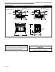
Radiance® Direct Vent Gas Heater Installation & Operating Instructions Requirements for the Commonwealth of Massachusetts All gas fitting and installation of this heater shall only be done by a licensed gas fitter or licensed plumber.
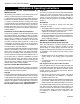
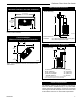
Radiance® Direct Vent Gas Heater Radiance Direct Vent Stove Dimensions See Page 7 for Flue Collar Centerline Dimensions. 14⁷⁄₈" (378 mm) 7" Outer Dia. (178 mm) Supply Inlet 4³⁄₄" (120 mm) Flue Collar C L 14⁷⁄₈" (378 mm) 7" Outer Dia. (178 mm) Supply Inlet 4³⁄₄" (120 mm) C L 9¹⁄₂" (241 mm) 8⁹⁄₁₆" (218 mm) Flue Collar RADVT Models 13³⁄₈” (340 mm) RADVTC Models 11” (279 mm) 29³⁄₄" (758 mm) RADIANCE 28" (711 mm) Supply Inlet 5" (127 mm) 18¹⁄₄" (464 mm) 31" (787 mm) Fig.
Radiance® Direct Vent Gas Heater Installation Requirements The installation must conform with local codes or, in the absence of local codes, with the National Fuel Gas Code, ANSI Z223.1/NFPA 54 - latest edition. (EXCEPTION: Do not derate this appliance for altitude. Maintain the manifold pressure at 3.5" w.c. for Natural Gas, and 10" w.c. for Propane). In Canada, installation must be in accordance with the current CSA B-149.1 Installation Codes and/or local codes.
Radiance® Direct Vent Gas Heater Parallel Installation: Minimum Clearance and Flue Centerline Wall Centerline from Floor Direct Vent Only 42" (1070mm) Min. Alcove Width 4" (102mm) 48" (1220mm) Max. Alcove Depth ST130 A 6" (150mm) 6" (150mm) Fig. 3 Parallel installation, minimum back and side clearances, and flue centerlines.
Radiance® Direct Vent Gas Heater Gas Specifications Weight: Fully assembled; 350 lbs. Gas Inlet and Manifold Pressures Inlet Minimum Natural 5.5" w.c. LP (Propane) 11.0" w.c. Inlet Maximum 14.0" w.c. 14.0" w.c. Manifold Pressure 3.5" w.c. 10" w.c. The installation of your Vermont Castings stove must conform with local codes, or in the absence of local codes, with the National Fuel Gas Code ANSI Z223.1/ NFPA 54 - latest edition, or CSA B149.1 Installation code.
Radiance® Direct Vent Gas Heater Restrictor Plate Adjustment for Extended Pipe Runs Vertical Termination A vertical vent system must terminate no less than 8’ (2.44 m) and no more than 40’ (12 m) above the appliance flue collar. A restrictor plate (supplied) must be used, where specified, in all vertically terminated vent systems. (Refer to Figure 8) NOTE: The restrictor plate supplied with the vertical termination should be discarded. Adjust the restrictor plate according to recommendations in Figure 10.
Radiance® Direct Vent Gas Heater Vent Termination Clearances When planning the installation, consider the location of the vent terminal and clearances. Some of the most common clearances to keep in mind are shown in Figure 11. Important: All vent clearances must be maintained. Check your vent termination clearances against Figures 11 through 13. The vent should be placed so that people cannot be burned by accidentally touching the vent surfaces when the stove is operating.
Radiance® Direct Vent Gas Heater General Venting Information - Termination Location INSIDE CORNER DETAIL V G N H A D L V E C B V F Ope B V Operable rable V B CFM145a V VENT TERMINATION B Fixed Closed B V V Fixed Closed J X B A X AIR SUPPLY INLET M I V K X AREA WHERE TERMINAL IS NOT PERMITTED Canadian Installations1 CFM145a DV Termin Location 12" (30 cm) 5/01/01 Rev.
Radiance® Direct Vent Gas Heater Termination Clearances Termination clearances for buildings with combustible and noncombustible exteriors. Alcove Applications* Inside Corner Outside Corner G= Combustible 6" (152 mm) G V Noncombustible 2" (51 mm) V F= Combustible 6" (152 mm) Noncombustible 2" (51 mm) F Balcony with perpendicular side wall Balcony with no side wall D C C V O E E = Min. 2” (51 mm) for non-vinyl sidewalls Min. 12” (305 mm) for vinyl sidewalls O = 8’ (2.4 m) Min.
Radiance® Direct Vent Gas Heater Venting Requirements and Options Approved Vent System Components The Radiance Heater must be vented to the outdoors through an adjacent exterior wall or through the roof. The venting system must be comprised of the appropriate listed venting components specified on this page. These parts are available from DuraVent Corporation, Selkirk Corporation or your Vermont Castings Dealer. See Figure 4 for dimensions relevant to the standard minimum-vent kits.
Radiance® Direct Vent Gas Heater Vermont Castings Group Vent Components The following kits are available to meet the needs of most installations. All pipe has a 7" outer diameter and includes a 4" diameter inner section. A (CG) designation indicates the part is finished in Charcoal Gray paint. Consult your dealer about other vent parts that may be appropriate to complete the installation. Min.
Radiance® Direct Vent Gas Heater Assembly Procedures WARNING Failure to position the parts in accordance with these diagrams or failure to use only parts specifically approved for use with this heater may result in property damage or personal injury. This heater and components are heavy. Have help available for assembly. Tools Required • • • • Phillips screwdriver (stub) • power drill utility knife • reciprocating saw metal drill bit: size 28 (.140"/3.
Radiance® Direct Vent Gas Heater WARNING This appliance is equipped with a three-prong (grounded) plug for your protection against shock hazard and should be plugged directly into a properly grounded three-prong receptacle. Do not cut or remove the grounding prong from this plug. Install the Optional Fan - RADVT Series If you are installing the optional convection Fan Kit #2767 (FK26), continue here. It is easiest to install fan kit before connecting gas line.
Radiance® Direct Vent Gas Heater Venting System Assembly General Information The Radiance is approved for installation only with the vent components listed on Pages 13 and 14. Follow the vent component instructions exactly. For U.S. installations: The venting system must conform with local codes and/or the current National Fuel Gas Code, ANSI Z223.1/NFPA 54. ENT CEM For Canadian installations: The venting system must conform to the current CSA B149.1 installation code.
Radiance® Direct Vent Gas Heater Inner Adpater Pipe 1/4-20 x 3/8" Phillips Screws Length will fit inside the flue outlet Secure with a minimum of two #8 x 1/4" sheet metal screws and seal with hi-temp silicone. For units factory equipped with appliance adapters from other brands of Direct Vent systems, it is permissible to simply slide a length of DT pipe over the appliance adapter. Secure with a minimum of two #8 x 1/4" sheet metal screws and seal with hi-temp silicone.
Radiance® Direct Vent Gas Heater 12" (305mm) Max. Length Sleeve X #8 Sheet Metal Screws ST215 Fig. 27 Measure the horizontal length. Firestop ZCS103 Fig. 25 Assemble the wall sleeve and firestop. 4. For VermontZCS103 Castings Group Vent Pipe only: If necZeroto Clearance Sleeve essary, measure determine the vertical length (X) of & Firestop pipe required from the adapter pipe to the wall cutout 12/6/99 adjt2" overlap at the joint. (Fig.
Radiance® Direct Vent Gas Heater 11. For Vermont Castings Group only: Install Charcoal Gray Pipe Rings (#7FSDRG) or Polished Brass Pipe Rings (#7FSDRP) at pipe joints, if desired. Vent Termination Below Grade Install Snorkel Kit #7FSDVSKS when it is not possible to meet the required vent termination clearances of 12" (305 mm) above grade level. The snorkel kit will allow installation depth of down to 7" (178 mm) below grade level.
Radiance® Direct Vent Gas Heater #7DVAIS Attic Insulation Shield #7DVFS Firestop in Upper Floor Use Four 8d Nails #7DVFS Firestop in Ceiling ST222 Fig. 32 Install firestops and attic insulation shield. 7. Install the appropriate roof support and flashing, makST222 ing certain that the vent upper thru flange ceiling of the flashing base is below the shingles.12/99 (Fig. 33) 8. Install appropriate pipe sections until the vent run reaches above the flashing.
Radiance® Direct Vent Gas Heater Gasket A round trim plate (TP) is attached to the ceiling, using screws, to provide a finished appearance once installed. (Fig. 35) Outlet End Inlet End Lock Tab To Termination To Appliance ST922 Fig. 34 Joint connection. Vent Termination (VC) Storm Collar (SC) Ceiling Support Collar Ceiling Support Plate ST922 Selkirk seal 6/07 Trim Plate ST923 Fig. 35 Ceiling support.
Radiance® Direct Vent Gas Heater The Cathedral Ceiling Support (CCS) may be used in pitched or flat ceiling installations and comes with a support collar and a decorative two part square trim plate. Install by inserting the support box down through the framed joist opening (end with round hole first) in the ceiling using tin snips, cut the corners of the open end of the box such that the sides can be folded down over the top of the joist framing members. Nail the folded sides to the top of the framing.
Radiance® Direct Vent Gas Heater less than 7’ (2.1 m) high. Refer to Pages 11, 12, Figures 11, 12 for more detail. Snorkel Termination Wall Thimble Shield Seal with RTV Silicone Sealant on Exterior side here (around perimeter) Wall Thimble Shield Window Well Maintain 2" (51 mm) Clearance Below Snorkel 12" (305 mm) Minimum Clearance Above Grade Level to Air Intake Grade Level Sloped Away From Building Wall Thimble Face Plate Wall Thimble Face Plate ST930 Adequate Drainage as per Local Codes Fig.
Radiance® Direct Vent Gas Heater ed straps of the horizontal termination provide a method of attachment. These can either be threaded through the opening or wall thimble (if used) and screwed to the pipe or removed with a pair of tin snips if not used. Use proper masonry fasteners to attach the horizontal termination to the wall. 7.
Radiance® Direct Vent Gas Heater 11. Add lengths of pipe and firestop as necessary until assembly extends to a point above the roof which complies with local code requirements for minimum termination height and with the appliance manufacturer’s installation instructions. (Fig. 45) NOTE: Whenever DIRECT-TEMP penetrates through a ceiling, a floor or a wall, it must be firestopped. 12. Using a level, make sure the system is perfectly vertical. 13.
Radiance® Direct Vent Gas Heater CAUTION: Before installation, inspect ember bed burner for damage. Do not use ember bed if damaged or cracked. NOTE: Small, shallow surface cracks are acceptable. 1. Remove the logs from their packaging and inspect each piece for damage. DO NOT INSTALL DAMAGED LOGS. 2. Install the rear log by placing it on the ember bed toward the back of the firebox. (Fig. 48) The log should touch the back wall of the firebox.
Radiance® Direct Vent Gas Heater Left Cross Log Rear Log Right Cross Log Figure 51 Front Right Log LG490 Front Left Log Connect the Gas Supply Line Ember Bed CAUTION Check the Rating Plate attached by a steel cable to the This appliance should only be connected firebox, to confirm that you have the appropriate firebox by a qualified gas technician. Test to LG490 for the type of fuel to be used.
Radiance® Direct Vent Gas Heater THIS APPLIANCE SHOULD BE CONNECTED TO THE GAS SUPPLY ONLY BY A QUALIFIED GAS SERVICE TECHNICIAN. FOLLOW ALL LOCAL CODES. THERE MUST BE A GAS SHUT-OFF BETWEEN THE STOVE AND THE SUPPLY. Install ON/OFF Switch - RADVT Series The switch assembly parts are found in the parts bag. 1. Attach switch assembly to left rear side of stove shroud (when facing shroud) using two screws and existing holes in shroud. (Fig. 52) 2.
Radiance® Direct Vent Gas Heater Install the Safety Barrier CERTIFIED SAFETY BARRIER NOTE: A barrier designed to reduce the risk of burns from the hot viewing glass is provided with this appliance and shall be installed for the protection of children and other at risk individuals. If the barrier becomes damaged, the barrier shall be replaced with the manufacturer's barrier for this appliance.
Radiance® Direct Vent Gas Heater Operation Your First Fire Read these instructions carefully and familiarize yourself with the burner controls shown on Page 32. Locate the pilot assembly, Figure 56. Follow the lighting instructions on Page 32 exactly. During the first fire, it is not unusual to smell some odor associated with new logs, paint and metal being heated. Odors should dissipate within the first eight to ten hours, however, you can open a window to provide fresh air to alleviate the condition.
Radiance® Direct Vent Gas Heater Lighting and Operating Instructions FOR YOUR SAFETY READ BEFORE LIGHTING WARNING:If you do not follow these instructions exactly, a fire or explosion may result causing property damage, personal injury or loss of life. A. This heater has a pilot which must be lit manually. When lighting the pilot follow these instructions exactly. B. BEFORE LIGHTING smell all around the heater area for gas.
Radiance® Direct Vent Gas Heater Troubleshooting the Gas Control System (RADVT Series) SIT NOVA 820 MILLIVOLT VALVE NOTE: Before trouble shooting the gas control system, be sure external gas shut off is in the “On" position. Symptom Possible Causes Corrective Action 1. Spark ignitor will not light A. Defective or misaligned electrode at pilot Using a match, light pilot. If pilot lights, turn off pilot and push the red button again.
Radiance® Direct Vent Gas Heater Instructions for RCSITEA Remote Transmitter RADVTCS Series Install Batteries CAUTION: The RCSITEA is only certified for use on vented heater rated equipment. The remote transmitter uses three (3) “AAA" batteries. This remote control system provides a safe, reliable and user-friendly remote control for millivolt valve gas appliances, blower speed and flame height adjustment. The system can be manually or thermostatically turned on and off with the transmitter.
Radiance® Direct Vent Gas Heater 3. To check, press either the ON or OFF button on the transmitter and the receiver indicator light will blink. If not, repeat Step 2. 4. The system is now ready to operate. NOTE: Refer to optional 6 Hour Shutdown. WARNING: Do not use two (2) or more remote control systems in the same area with the same dip switch settings, they will communicate with each other. This may cause the appliances to malfunction.
Radiance® Direct Vent Gas Heater Initial Startup Figure 62 1. After initial power up or when RESET button is °F pressed, the transmitter is reset. The reset button is located behind the battery door of transmitter. 2. During system reset, all feaFP2142 tures of the LCD DISPLAY Fig. 62 Typical Reset will be visible. After one Display FP2142 second, the LCD will be start initialized. A typical reset display isinitial shown in up Figure 60. Note the temperature scale is degree F. 3.
Radiance® Direct Vent Gas Heater minutes. 2. Use the ON /s button to set the desired On Delay Time from 0 to 15 minutes. 3. Use the OFF / t button to set the desired Off Delay Time from 0 to 15 minutes. 4. If there is no input within 3 seconds, the new setFP2146 ting will be transmitted to Fig. 67 Blower time delay receiver. display. FP2146 5. The default settings for blower delay timer both transmitter and receiver are 12/08 5 minutes for ON delay time and 8 minutes for OFF delay time.
Radiance® Direct Vent Gas Heater Testing Remote Control System 1. Light the gas appliance following the lighting instructions on Page 32. Confirm the pilot light is on; it must be in operation for the remote control to operate the main gas valve and blower. Appliance control knob must be in the ON position, and ON/OFF switch must be in OFF position. 2. Slide the 3 position button on the remote receiver to the ON position and the main gas flame should ignite. 3.
Radiance® Direct Vent Gas Heater Fuel Conversion Instructions ST226a Fig. 71 Attach the gas line to the right side of the valve. Conversion Precautions ST226 Before proceeding, turn control knob on valve to OFF and attach gas line turn gas supply OFF. Turn OFF any electricity that may be 12/8/99 djt going to the appliance. Conversion Procedure 1. Remove stove front. Lift stove front up and then swing bottom out and away to disengage from the stove body. 2.
Radiance® Direct Vent Gas Heater RADVTCS Series Models 1. Using the TORX T20 bit remove and discard the three (3) pressure regulator mounting screws from the old pressure regulator assembly. (Fig. 77) 2. Replace pilot orifice. 3. Remove pilot hood by lifting up. (Fig. 79) Do not remove the snap ring to remove the pilot hood. NOTE: It is not necessary to remove the pilot tube for conversion. 4. Remove pilot orifice with Allen wrench. (Fig. 80) Pilot Hood Pilot Bracket CO105a Fig. 79 Remove pilot hood.
Radiance® Direct Vent Gas Heater Orifice Bracket Venturi Bracket Orifice Bracket Orifice Air Shutter CO142 Pem Studs ST919 Fig. 82 Tilt ember bed slightly to correctly place on venturi and air shutter. 2. Carefully remove ember bed by tilting the right side up ST919 and lifting out toward the right side of the unit. (Fig. 82) tilt ember bed 3. Remove injector orifice from left burner bracket with a 6/07 1/2" wrench. Use a back up wrench to prevent damage to the manifold. (Fig. 83) 4.
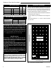
Radiance® Direct Vent Gas Heater Table 2. Injector Orifice Size Matrix Conversion to LP Input (BTU/h) Model Kit # Orifice Part # Minimum Maximum RADVT 20012729 RADVTCS 1.75 mm 20012946 25,000 36,000 #31 / 0.120" 20006927 25,000 38,000 20300165 Conversion to Natural Gas Input (BTU/h) Model Kit # Orifice Part # Minimum Maximum RADVT 20012899 RADVTCS 20300166 Table 3.
Radiance® Direct Vent Gas Heater Maintenance Your Radiance Gas Heater will provide years of service with minimal upkeep. The following procedures will help ensure that your stove continues to function properly. Annual System Inspection Have the entire heater and venting system inspected annually by a qualified gas technician. Replace any worn or broken parts. Logset and Burner / Cleaning and Inspection Cleanliness is critical to the proper function of the heater.
Radiance® Direct Vent Gas Heater Glass Replacement Replace glass only with Vermont Castings Group approved parts. Refer to Replacement Parts section for correct glass. Refer to Figure 85 and previous instructions for removal of the damaged glass frame. 3. Starting on a long edge, remove about 6" of the protective paper strip and apply the flat adhesive face of the gasket around the outside-facing edge of the panel.
Radiance® Direct Vent Gas Heater Wiring Diagrams - RADVT OFF ON Thermopile Black On/Off Switch Wiring TP/TH BL Millivolt Gas Valve TP Black TH FAN POWER CORD Chassis Ground ST124b Thermostat K BLK FAN JUNCTION BOX St124b on/off/switch wiring 1/11/00 djt TP TH BL Thermopile Black TP/TH K GRN Thermostat (Optional) (Optional) Optional Thermostat Wiring BLK WHT Strain Relief ON / OFF Rheostat Millivolt Gas Valve Black Snapstat ST124c Fig.
Radiance® Direct Vent Gas Heater Wiring Diagrams - RADVTCS Black 120V AC Adapter Black mV Valve TH T P /TH Receiver 120V AC Plug Female Male SIT HI / LO Valve 120V AC Blower ST1091 Fig. 91 SIT Hi/Lo blower schematic. ST1090 120V AC Plug for Receiver SIT valve wiring SIT mV Valve Receiver Tag Tag Tag: to blower Tag: to 120V AC Hi/Lo Regulator Blower 120V AC Plug for Blower ST1092a Fig. 92 SIT Hi/Lo blower wiring.
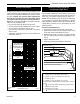
Radiance® Direct Vent Gas Heater Radiance Direct Vent Gas Heater Replacement Parts 1 5 1a 7 1b 8 4 1c 6 3 1e 1d 10 9 11 22 21 24 2 20 19 15 14 12 16 17 34a,b 35a,b,c 7 29 30 23a 27a,b 18 50a 28 31 50 23b 26a,b 32 13 33 39 38 52 44 45 47 42 49 41 36 ON N FA TO E AU AM FL F OF ON RS OF F 40 25 48 4967 Vermont Castings Group reserves the right to make changes in design, materials, specifications, prices and discontinue colors and products at any RADVT/RADVTCS parts
Radiance® Direct Vent Gas Heater Radiance Direct Vent Gas Heater (continued) Replacement Parts Ref. Description 1. Log Set - Complete 1a. Log, Rear 1b. Log, Right Front 1c. Log, Left Front 1d. Left Cross Log 1e. Right Cross Log 2. Ember Bed Assembly 3. Top 4. Screen, Top 5. Grille 6. Front II 7. Door, Left 8. Door, Right 9. Control Door 10. Left End 11. Right End 12. Leg 13. Glass Frame Assembly 14. Frame, Glass 15. Gasket, Glass Med. Knit 16. Glass, GFP Firebox 17. Wood Handle 18.
Radiance® Direct Vent Gas Heater Radiance Direct Vent Gas Heater (continued) Replacement Parts Ref. Description RADVT/RADVTCS 36. 37. 38. 39. 40. 41. 42. 44. 45. 46. 47. 48. 49. 50. 50a. 51. Ignitor Piezo w/ Nut SIT Bracket Piezo Ignitor/Control (not shown) Manifold Assembly Air Shutter Assembly Trim ON/OFF Switch Remote Kit (Hi/Lo, Blower) (RADVTCS Series only) Wire w/ Straight Term 2 End 50" Gasket Base Pan Gasket, HE Door Gasket Cement, 3 oz.
Radiance® Direct Vent Gas Heater Optional Accessories Fan Kits - RADVT Series FK26 Fan The FK26 fan helps distribute heated air from within the firebox out into the room. The fan is controlled by a snapstat that turns power on and off as the firebox temperature rises above and falls below a preset temperature. A rheostat provides for variable fan speeds. Used with standard millivolt models. Specifications 115 Volt / 60Hz / .
Radiance® Direct Vent Gas Heater LIMITED LIFETIME WARRANTY PRODUCT COVERED BY THIS WARRANTY All Vermont Castings brand gas stoves, gas inserts, and gas fireplaces installed in the United States of America or Canada.
EFFICIENCY RATINGS MODEL ENERGUIDE RATINGS FIREPLACE EFFICIENCY PERCENTAGE D.O.E. (AFUE PERCENTAGE) RADVT Series 66.0 68.4 RADVTCS Series 66.0 68.4 149 Cleveland Drive • Paris, Kentucky 40361 www.vermontcastingsgroup.