Decorative Gas Fireplace Models: NVC36, NVC39, NVC43 INSTALLER/CONSUMER SAFETY INFORMATION PLEASE READ THIS MANUAL BEFORE INSTALLING AND USING APPLIANCE IMPORTANT: Read all instructions and warnings carefully before starting installation. Failure to follow these instructions may result in a possible fire hazard and will void the warranty. WARNING: If the information in this manual is not followed exactly, a fire or explosion may result causing property damage, personal injury or loss of life.
NVC Series B-Vent Table of Contents Thank you and Congratulations on your purchase of a CFM Corporation fireplace. PLEASE READ THE INSTALLATION & OPERATING INSTRUCTIONS BEFORE USING THE APPLIANCE IMPORTANT: Read all instructions and warnings carefully before starting installation. Failure to follow these instructions may result in a possible fire hazard and will void the warranty. Installation Instructions General Information, Warnings, Cautions ...............................................................
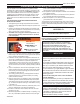
NVC Series B-Vent Installation & Operating Instructions This gas appliance must be installed by a qualified installer, preferably NFI or WETT (Canada) certified, in accordance with local building codes and with current CSA-B149.1 Natural Gas and Propane Installation Code. If the unit is being installed in a mobile home, the installation should comply with the current CAN/CSA Z 240.4 code. For U.S.A Installations follow local codes and/or the current National Fuel Gas Code ANSI Z223.1/ NFPA 54.
NVC Series B-Vent Installation & Operating Instructions Requirements for the Commonwealth of Massachusetts All gas fitting and installation of this heater shall only be done by a licensed gas fitter or licensed plumber.
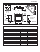
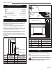
NVC Series B-Vent Fireplace Dimensions N INSET A K 10" 5���" 7���" 3���" CL 6" Flue P L A 10" = 254mm 7���" = 187mm 5���" = 149mm 3���" = 92mm Finished Wall Thickness Rough Opening Width N M Rough Opening Height Gas Line Access 2" Dia. Gas Line Access - 2" Dia. Electrical Cable Knock-out 1" Dia. U V Electrical Cable Knock-out - 1" Dia. S B E Electrical Box Knock-out - 2" Dia.
NVC Series B-Vent Clearance to Combustibles Appliances Top .......................................................... 0” (0 mm) Bottom ..................................................... 0” (0 mm) Side ......................................................... 0” (0 mm) Back ........................................................ 0” (0 mm) Perpendicular Sidewall ........................... 0” (0 mm) Top of unit to ceiling .......................... 36” (914 mm) Front of unit to combustibles .............
NVC Series B-Vent Framing and Finishing Gas Specifications Check fireplace to make sure it is levelled and properly positioned. 1. Choose the unit location. 2. Place the unit into position and secure it to the floor with 1¹⁄₂” (38mm) screws, or nails. The holes to secure the unit to floor are located just behind the access door grille on the left and right side of the unit. 3. Frame in the fireplace with a header across the top.
NVC Series B-Vent Gas Line Installation 1/2" Gas Supply When purging gas line the fornt glass must be removed. Purging gas lines must comply with ANSI Z223.1/NFPA 54 in USA and CSA B149.1 in Canada. The gas pipeline can be brought in through the right or left side of the appliance, as well as the bottom. Knockouts are provided at convenient locations to allow for the gas pipe installation and testing of any gas connection.
NVC Series B-Vent EB-1 Electrical Box Inside The fireplace, when installed, must be electrically connected and grounded in accordance with local codes or, in the absence of local codes, with the current CSA C22.1 Canadian Electrical Code Electrical Box Retaining Screw Front of For USA installations follow the local codes and the national electrical code ANSI/NFPA No. 70. It is strongly suggested that the wiring of the EB-1 Electrical Junction Box be carried out by a licensed electrician.
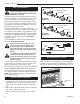
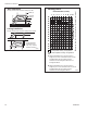
NVC Series B-Vent Horizontal Run (in feet) Nails (4) 3 4 Firestop Spacer 40 38 36 34 Joist 5 6 7 8 9 10 11 12 A B 32 Ceiling Installation Firestop position when area above ceiling is NOT an attic. 30 28 26 24 22 (Firestop/draftstop appearances may vary. Only 1 firestop required per frame.) FP384 Fig. 9 Firestop/draftstop positions. FP384 FIRESTOP 11/21/96 adapted from IGF53 Vertical Run (in feet) (Measured from floor of unit tocenter of horizontal vent pipe.
NVC Series B-Vent Operating Instructions Glass Information Only glass approved by CFM Corporation should be used on this fireplace. • The use of any non-approved replacement glass will void all product warranties. • Care must be taken to avoid breakage of the glass. • Do not operate appliance with glass front • removed, cracked or broken. Replacement glass (complete with gasket) is available through your CFM Corporation dealer and should only be installed by a licensed qualified service person.
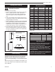
NVC Series B-Vent NVC39 BC5 BC6 BC7 BC8 BC9 NVC43 BD6 BD7 BD8 BD9 BD10 BB9 Log Top Left BE5 Log Rear BB10 Log Top Right BB6 Log Front Left BB7 Log Front Rigth NVC36 BC8 Log Top Left BC9 Log Top Right BC7 Log Rear FP NVC36 LOG SET 8-11-98 BC5 Log Front Left BC6 Log Front Right BD9 Log Top Left NVC39 LOG SET BD10 Log Top Right 8-12-98 Ember Material Placement Separate the ember material into small pieces, roughly 1/2" in diameter, and place onto the burner in front of the front logs.
NVC Series B-Vent Test Chimney Draw NVC36 A "Chimney Draw" test must be made before the installation is complete. 1. Close all doors and windows in the home and start exhaust fans in the kitchen and bathroom. 2. Light unit and operate for 5 minutes. 3. Hold an ignited match, cigarette, or smoke match in front of the unit. Refer to Figure 17 for location of the draft hood opening. 4. Check to make sure smoke from the match, cigarette or smoke match is drawn into the fireplace.
NVC Series B-Vent Lighting and Operating Instructions FOR YOUR SAFETY READ BEFORE LIGHTING WARNING:If you do not follow these instructions exactly, a fire or explosion may result causing property damage, personal injury or loss of life. A. This heater has a pilot which must be lit manually. When lighting the pilot follow these instructions exactly. B. BEFORE LIGHTING smell all around the heater area for gas. Be sure to smell next to the floor because some gas is heavier than air and will settle on the floor.
NVC Series B-Vent Vent Safety Switch Electrical Connection This fireplace incorporates the use of a Vent Safety Shut-off Switch. The sensor and wiring are factory installed and should not be removed or altered during installation. The sensor is wired in series between the wall mounted ON/OFF switch and the Electronic Ignition Module (Fig. 19) or the thermopile and the gas valve (Fig.
NVC Series B-Vent Troubleshooting Honeywell Electronic Ignition START Turn gas supply off Turn ON/OFF Switch to call for heat. NO CHECK : Power to module (24V nominal) YES Spark across Ignitor Sensor gap NO Line Voltage (120VAC) Low Voltage Transformer (19.5 minimum VAC) ON/OFF Switch Wiring connections Thermodisk Unplug Ignition Lead and check spark at module (24VAC nominal) NO Replace Module Spark OK? YES YES Check ignition cable, ground wiring, Ceramic Insulator and gap.
NVC Series B-Vent Troubleshooting Honeywell VS8421 Remove glass door before service work CHECK START Gas Supply On NO • Supply Line Hooked Up • Shutoff Valve Open YES • Lockout Has Engaged. Wait 60 Seconds And Try Again. • For Spark At Electrode While Pilot Lights With Piezo Ignitor NO • • Depressing Piezo 1/8" Gap To Pilot Hood Needed. All Wiring Connections Replace Piezo Ignitor YES • For Air In The Lines • Thermopile Needs A Min. Pilot Stays Lit NO • • • • YES 325mv.
NVC Series B-Vent Troubleshooting Nova SIT 820 Standing Pilot START Gas Supply On CHECK NO Supply Line Hooked Up Shutoff Valve Open YES Pilot Lights With Piezo Ignitor NO YES Pilot Stays Lit NO Lockout Has Engaged. Wait 60 Seconds and Try Again. Piezo Nut Tight for Good Ground. For Spark at Electrode While Depressing Piezo (Red Button) - 1/8" Gap to Pilot Hood Needed. All Wiring Connections Replace Piezo Ignitor Check thermodisk For Air in the Lines Thermopile Needs a Minimum 325Mv.
NVC Series B-Vent Maintenance Burner and Burner Compartment It is important to keep the burner and the burner compartment clean. At least once per year the logs and lava rock/ember material should be removed and the burner compartment vacuumed and wiped out. Remove and replace the logs as per the instructions in this manual. Always handle the logs with care as they are fragile and may also be hot if the fireplace has been in use.
NVC Series B-Vent NVC43 Logs 1 NVC39 1 NVC36 1e 1d 1e 1d 1e 1d 1c 1c 1c SIT Valve 1a 15-16a/b � ������ ��� � ��� TH ��� � ��� �� �� ������ �� � ������� ���� NOVA SIT 822 VALVE � TP ����� 20/21 � � � � �� �� THTP 6a/b 1b � 18 3 2 1b 1a 1b 1a ����� �� ���� � � � ������ ����� � � ��� � GND (BURNER) 24V 24V SENSE �� 13 8a/b 14 27 5 10 SPARK � PV �� ��� � ����� �� � � MVPV � ��� � MV � ��������� � � �� �� 7a/b 4a/b 17a/b ����� ������ ����� �
NVC Series B-Vent NVC36/39/43 (continued) Ref. 4a. 4b. 5. 6a. 6b. 7a. 7b. 8a. 8b. 9. 10. 11a. Description Burner Housing w/tile-Nat Burner Housing w/tile-LP Ceramic tile (Single) Orifice Front Burner-Nat. Orifice Front Burner-LP Pilot Assy- SIT Top Convertible, LP Pilot Assy - SIT Top Convertible, Nat. Orifice Pilot - Nat. Orifice Pilot - LP Pilot Tubing w/Fittings Electrode Ignitor Cable Ignitor (RNRP/VN/VP) 24” 11b. 12. 13. 14. 15a. 15b. 16a. 16b. 17a. 17b. 18. 19. 20. 21. 22. 23. 24. 25. 26. 27. 28. 29.
NVC Series B-Vent NVC36/39/43 (continued) Ref. 40a. 40b. 41. 22 Description Valve - Honeywell VS8421 - Nat.
NVC Series B-Vent Optional Accessories Fan Kits FK12 Fan Assembly 1. Open louvre assembly bottom. 2. Install FK12 fan in back of unit between hearth supports. The fireplace, when installed must be electrically connected and grounded in accordance with local codes or, in the absence of local codes, with the current CSA C22.1 Canadian Electrical Code or for US installations, follow local codes and the National Electrical Code, ANSI/NFPA No. 70. Hard (Direct) Wire Hook-Up 3. Secure fan on velcro strips. 4.
NVC Series B-Vent Remote Controls Optional remote control units are available to control different functions of the appliance. Model RC1 RC2 IMTFK Function(s) Controlled ON/OFF ON/OFF and Temperature Wall mounted thermostat control Ceramic Refractory Panels Ceramic refractory panels are available to line the firebox area. Unit NVC36 NVC39 NVC43 Kit Model NV36CR NV39CR NV43CR Take care when handling the refractory panels as they are fragile until held in place and supported.
NVC Series B-Vent Louvre Assembly Top Bay Window Frame Ceramic Ceramic Refractory Refractory Spacers FP1196 Fig. 28 Arched door front in place. Decorative FP1195 Bay Windows door front When fitting the Arched Bay Window Kits, the original 2/27/02 djt front frame/glass assembly MUST remain in place. The Bay Window kit is fitted over the existing front glass. Installation 1. Remove the existing louvre assembly bottom complete with the hinges. 2. Remove the louvre assembly top. 3.
NVC Series B-Vent 26 20000194
LIMITED LIFETIME WARRANTY NVC Series B-Vent PRODUCT COVERED BY THIS WARRANTY All Vermont Castings gas stoves, gas inserts, and gas fireplaces, and all Majestic or Northern Flame brand gas fireplaces equipped with an Insta-Flame Ceramic Burner, or standard steel tube burner.
Efficiency Ratings Model NVC36RN NVC36RP NVC36RFN NVC36RFP NVC36EN NVC36EP NVC39RN NVC39RP NVC39RFN NVC39RFP NVC39EN NVC39EP NVC43RN NVC43RP NVC43RFN NVC43RFP NVC43EN NVC43EP EnerGuide Ratings Fireplace Efficiency (%) 29.4 29.4 29.4 29.4 28.5 28.5 26.4 26.4 26.4 26.4 25.6 25.6 27.9 27.9 27.9 27.9 27.1 27.1 CFM Corporation 2695 Meadowvale Blvd. • Mississauga, Ontario, Canada L5N 8A3 800-668-5323 • www.cfmcorp.