Decorative Gas Appliance Model: NV360 NV580 INSTALLER/CONSUMER SAFETY INFORMATION PLEASE READTHIS MANUAL BEFORE INSTALLING AND USING APPLIANCE. WARNING: IF THE INFORMATION IN THIS MANUAL IS NOT FOLLOWED EXACTLY, A FIRE OR EXPLOSION MAY RESULT CAUSING PROPERTY DAMAGE, PERSONAL INJURY OR LOSS OF LIFE. FOR YOUR SAFETY Installation and service must be performed by a qualified installer, service agency, or the gas supplier.
NV360/580 Series Table of Contents Thank you and Congratulations on your purchase of a Majestic Fireplaces fireplace. PLEASE READ THE INSTALLATION & OPERATING INSTRUCTIONS BEFORE USING THE APPLIANCE IMPORTANT: Read all instructions and warnings carefully before starting installation. Failure to follow these instructions may result in a possible fire hazard and will void the warranty. Installation & Operating Instructions General Information.....................................................................
NV360/580 Series Installation & Operating Instructions This gas appliance should be installed by a qualified installer in accordance with local building codes and with current CSA-B149.1 Installation codes for Gas Burning Appliances and Equipment. If the unit is being installed in a mobile home, the installation should comply with the current CAN/CSA Z 240.4 code. For U.S.A. installations follow local codes and/or the current National Fuel Gas Code ANSI Z223.1/NFPA 54.
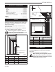
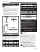
NV360/580 Series Fireplace Dimensions Rough Opening Depth � J R � � � � � K Recessed CL Nailing Flange T - Rough Opening Width � Rough Opening Height � G F Outside Air S B L D C P E M O Electrical Access Gas Line Access N A G Q Fig. 1 Fireplace specifications and framing dimensions. 4 3565a Ref.
NV360/580 Series Clearance to Combustibles Appliances Top .......................................................... 0” (0 mm) Bottom ..................................................... 0” (0 mm) Side ......................................................... 0” (0 mm) Back ........................................................ 0” (0 mm) Perpendicular Sidewall ........................... 0” (0 mm) Top of unit to ceiling .......................... 36” (914 mm) Front of unit to combustibles .............
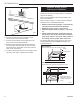
NV360/580 Series Air Shutter Setting Framing and Finishing Check appliance to make sure it is levelled and properly positioned. 1. Choose unit location. 2. Nailing flanges are supplied with the fireplace (found on the fireplace hearth). To level the box and secure it firmly in place, remove the nailing flanges from the hearth and install at the sides of the firebox as shown in Figure 3. 3. Screw through the slotted holes in the drywall strip and into pre-drilled holes in fireplace side.
NV360/580 Series Alternate Switch Location 1/2" Gas Supply The remote switch can be installed on either side of the access door. Mount the switch to the switch bracket provided. Screw the bracket on either side of the frame, line up the screws with the prepunched holes. (Fig. 6) 1/2" NPT x 3/8" Flare Shut-off Valve 3/8" Flex Line (from valve) FP297a Fig. 4 Typical gas supply installation. The fireplace valve must not be subjected to any test pressures exceeding 1/2 psi.
NV360/580 Series INSIDE FRONT Install the Venting System, Flashing and Termination Electrical Box NOTE: The NV360 uses a 6" B-vent system. The NV580 uses an 8" B-vent system (refer to Accessories, Page 23 for adapter). OF UNIT Refer venting installation instructions provided by the B-Vent manufacturer. Refer to Page 4, Figure 1 to locate chimney centerline dimension from a combustible back wall. OUTSIDE • Minimum vertical chimney height — 12 feet (3.65 m).
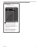
NV360/580 Series Venting Runs Horizontal Run (in feet) 1 40 38 36 34 32 2 3 4 5 6 7 8 9 10 11 12 Vertical Run (in feet) A B 30 28 26 24 22 20 18 16 14 12 = Acceptable venting configuration = Unacceptable venting configuration A: Vertical installations up to 40 feet (12m) in height. Up to an 8 ft. horizontal vent run can be installed within the vent system using a maximum of two (2) 90-degree elbows or four (4) 45-degree elbows. B: Vertical installations up to 40 feet (12m) in height.
NV360/580 Series Operating Instructions Glass Information Glass Frame Only glass approved by CFM Corporation should be used on this fireplace. • The use of any non-approved replacement glass will • • • void all product warranties. Care must be taken to avoid breakage of the glass. Do not operate appliance with glass front removed, cracked or broken.
NV360/580 Series 1. Remove window frame assembly. (Refer to Page 10) 2. Remove logs from packaging. As with all plastics - these are not toys and should be kept away form children and infants. 3. Place rear log on rear bracket (ensure log is seated properly, leveled and centered to the unit), so it will not move form side to side and is firmly positioned on the bracket. Be sure log is as far back as possible on bracket. 4. Place front left log on top of burner, left side.
NV360/580 Series Inspecting the Venting System LO Turn counterclockwise to increase flame height HI Turn clockwise to decrease flame height HV102 Fig. 13 Flame adjustment knob for Honeywell valve. Turn counterclockwise to increase flame height IH Turn clockwise to decrease flame height HV102 LO Honeywell hi/lo knob 4/5/99 djt Fig. 14 Flame adjustment knob for SIT 820 valve.
NV360/580 Series is not, turn the unit off and check for causes creating the lack of adequate draft. Do not operate the unit until lack of adequate draft has been determined and rectified. Test for Draft at This Location CAUTION: The firebox, Vent Safety Switch sensor and surrounding panels become very hot during normal operation. Allow time for the components to cool before carrying out any service or inspection.
NV360/580 Series WHITE PILOT MVPV PV GND (BURNER) 24V GND 24V BLACK HONEYWELL S8600 B IGNITION MODULE MV SPARK SENSE WHITE WHITE BLACK BLACK WHITE BLACK WHITE A E HI LO LO T HI PILO NOVA SIT 822 VALVE BLACK 24 VAC HOT 120 VAC RTN 1 5 WHITE 3 4 BLACK WHITE WHITE "ON/OFF" SWITCH 24 VAC RTN 120 VAC HOT GREEN BLACK BLACK 40VA TRANSFORMER FP670 Fig. 19 Vent Safety Switch wiring, EN/EP units. Thermopile "ON/OFF" Switch FP670 NOVA SIT 822 VALVE WIRING DGRM.
NV360/580 Series Lighting And Operating Instructions FOR YOUR SAFETY READ BEFORE LIGHTING WARNING:If you do not follow these instructions exactly, a fire or explosion may result causing property damage, personal injury or loss of life. A. This heater has a pilot which must be lit manually. When lighting the pilot follow these instructions exactly. B. BEFORE LIGHTING smell all around the heater area for gas. Be sure to smell next to the floor because some gas is heavier than air and will settle on the floor.
NV360/580 Series Troubleshooting Honeywell VS8420 Standing Pilot Remove Glass Panel Before Servicing. START Gas Supply ON CHECK NO • Supply line hooked up • Shutoff valve open NO • Lockout has engaged. Wait 60 seconds and try again. • For spark at electrode while depressing Piezo - 1/8" gap to pilot hood needed. • All wiring connections • Replace Piezo ignitor NO • For air in lines • Thermopile needs a minimum 325mV. Adjust pilot flame height.
NV360/580 Series Troubleshooting SIT NOVA 820 MILLIVOLT VALVE NOTE: Before troubleshooting the gas control system, be sure external gas shut off is in the "ON" position. WARNING: BEFORE DOING ANY GAS CONTROL SERVICE WORK, REMOVE GLASS FRONT. SYMPTOM 1. Spark ignitor will not light. POSSIBLE CAUSES A. Defective or misaligned electrode at pilot. B. Defective ignitor (push button) 2. Pilot will not stay lit after carefully following lighting instructions. A.
NV360/580 Series To convert the DV360/580 units for use with a different gas follow these instructions. Before proceeding, turn control knob on valve to “OFF” and turn gas supply OFF. Turn OFF any electricity that may be going to the appliance. CAUTION: Logs may be HOT! Allow to cool before proceeding. 2. Insure the rubber gasket (D) is properly positioned and install the new HI/LO pressure regulator assembly to the valve using the new screws (E) supplied with the kit. Tighten the screws securely. (Ref.
NV360/580 Series 4. Remove both air shutters from burner pan by removing shutter retaining screw then air shutter. (Fig. 26) 5. Install air shutters supplied in kit on burner pan. Replace shutter retaining screw. For conversion to Natural Gas adjust new air shutters so slots are covered. For conversion to Propane Gas, adjust new air shutters so slots are open. NOTE: NV360 air shutter has only one hole, closed. Secure shutter retaining screws. (Fig. 27) 6. Re-install manifold to burner pan.
NV360/580 Series Maintenance Burner and Burner Compartment It is important to keep the burner and the burner compartment clean. At least once per year the logs and lava rock/ember material should be removed and the burner compartment vacuumed and wiped out. Remove and replace the logs as per the instructions in this manual. Always handle the logs with care as they are fragile and may also be hot if the fireplace has been in use. FK24/FK12 Fan Assembly The fan unit requires periodic cleaning.
NV360/580 Series 1c 1c 1b 1a 5a,b 2 1a 1g 1b 6 4 14 3 15 1d 1d 7 1e DV360 DV580 1e 1f 11 19 16 8a 21a-d 9 13 8b 10a 12 10b 17 22 26 33 27 20 36a 36b I 34a/b ON T OFF 40 29 O PIL 28 35 O H 25 L 32 41 PILOT ADJ 37 31 18 42 38 46a,b 23 a/b 45 24 a/b 39 CFM Corporation reserves the right to make changes in design, materials, specifications, prices and discontinue colors and products at any time, without notice. NV360/580 Ref. 1. 1a. 1b. 1c. 1d. 1e.
NV360/580 Series NV360/580 (continued) Ref. 6. 7. 8a. 8b. 9. 10a. 10b. 11. 12. 13. 14. 15. 16. 17. 18. 19. 20. 21a. 21b. 21c. 21d. 22. 23a. 23b. 24a. 24b. 25a. 25b. 26. 27. 28. 29. 31. 32. 33. 34a. 34b. 35. 36a. 36b. 37. 38. 39. 40. 41. 42. 43.
NV360/580 Series NV360/580 (continued) Ref. Description 44. 45. 46a. 46b.
NV360/580 Series Accessories Front of Unit Hearth Pan Base Pan FK12 Fan FP1004 Fig. 32 FK12 Fan Kit placement. Hard (Direct) Wire Hook Up First connect ground wire to ground stud located on the base of either box. Black wire from supply should connect to the variable speed switch. Alternate speed switch wire connects to temperature sensor. Alternate lead from sensor connects to fan. Alternate fan lead connects back to the white supply wire. (Fig.
NV360/580 Series Remote Controls Optional remote control units are available to control different functions of the appliance. Model RC1 RC2 MRC3 IMT Functions Controlled ON/OFF ON/OFF and Temperature ON/OFF and Temperature control with a digital display and a programmable 24 hour clock Wall mounted thermostat control Rear Ceramic Panel Burner Rear Log Support Ceramic Refractory Lining H102 1. Remove glass and logs. 2. Insert supports under ceramic hearth panels. (Fig. 35) 3.
NV360/580 Series 26 20003565
LIMITED LIFETIME WARRANTY NV360/580 Series PRODUCT COVERED BY THIS WARRANTY All Vermont Castings gas stoves, gas inserts, and gas fireplaces, and all Majestic or Northern Flame brand gas fireplaces equipped with an Insta-Flame Ceramic Burner, or standard steel tube burner.
CFM Corporation 2695 Meadowvale Blvd. • Mississauga, Ontario, Canada L5N 8A3 800-668-5323 • www.cfmcorp.