
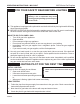
Operating instructions


75D0004 31
MLDV Series Gas Fireplace
5. Remove hearth brick and wall brick panels.
6. Disconnect the gas line to the valve.
7. Remove screws securing engine base to rebox oor
and lift engine up to remove.
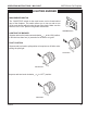
8. Two () magnetic strips have been supplied to secure
each blower to the rebox oor. Place on bottom of
each blower before installing. Figure 50
9. The blowers are to be inserted at through the engine
cutout in the rebox oor. Slide each blower over to the
sidewall location. Figure 51
Figure 53 -
Thermal Sensor Installation
Figure 54 -
Location of White Dial on Speed Control
KT503
blower magnets
11/08
Magnet
KT503
Figure 50 -
Magnet Installation
KT505
install blower
KT505
Figure 52 -
Blower Installation Position
FP1981
blower install
Figure 51 -
Blower Installation
FP1981
10.Turn blowers with discharge vent facing up. Slide the
discharge vent so that it is facing up. Slip discharge
vent ange under the ange bracket ush against the
sidewall. Slide blower side tabs over into side ange.
Figure 52. The blower is now locked in place.
11. Attach the speed control to the underside of the re-
box using the supplied velcro, locating as far to the
right or left as possible.
1. The thermal sensor clip is located beneath the rebox
oor near the center. Slide the thermal sensor into the
clip until it snaps in place. Make sure the terminals
on the thermal sensor are perpendicular to the clip.
Figure 53
It is important to arrange the blower wire har-
ness so the wires can not come in contact with blower
fan blades.
13. Connect wiring according to the wiring diagram Fig-
ure 55.
14. Replace engine in reverse order of removal.
15. Plug in the blower.
16. Re-install rebrick, grate, logs, and glass door in re-
verse order of removal.
17. To test blower operation, set the variable speed blow-
er on the LOW setting. Turn the replace on high. The
blower should turn on within 10 minutes.