
Operating instructions


75D0004 3
MLDV Series Gas Fireplace
FP1969
firestop w room above
Figure 34 -
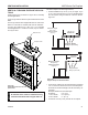
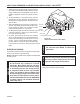
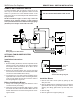
If Area Above is a Room, Install Firestop
above Framed Hole as Shown
Firestop
Nails
FP1969
10
1
/
2
"
10
1
/
2
"
FP1970
firestop no room
Figure 33 -
If Area Above is Not a Room, Install Firestop
above Framed Hole as Shown
Nails
Firestop
FP1970
Otherwise, install restop below the framed hole. The
restop should be installed with no less than three (3)
nails per side. Figure 34.
. Assemble the desired lengths of pipe and elbows nec-
essary to reach from the burner system ue up through
the restop. Be sure pipe and elbow connections are
fully twist-locked. Page 18, Figure 15.
3. Cut a hole in the roof using the locating hole as a center
point. (Cover any exposed open vent pipes before cut-
ting hole in roof). The 10Z\x" x 10Z\x" (67 x 67 mm)
hole must be measured on the horizontal. Actual length
may be larger depending on the pitch of the roof. There
must be a 1" minimum clearance from the vent pipe to
combustible materials. (Insulation should be considered
a combustible material). Frame the opening as shown
on Page 18, Figure 16.
4. Connect a section of pipe and extend up through the
hole.
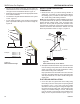
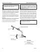
If an offset is needed to avoid obstructions, you
must support the vent pipe every three (3) feet. Use wall
straps for this purpose. Figure 32. Whenever possible, use
45° elbows instead of 90° elbows. The 45° elbow offers less
restriction to the ow of the ue gases and intake air.
5. Place the ashing over the pipe section(s) extending
through the roof. Secure the base of the ashing to
the roof and framing with roong nails. Be sure roong
material overlaps the top edge of the ashing. There
must be a 1" clearance from the vent pipe to combus-
tible materials.
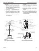
6. Continue to add pipe sections until the height of the
vent cap meets the minimum requirements below.
You must increase vent height for steep roof
pitches. Nearby trees, adjoining roof lines, steep pitched
roofs, and other similar factors may cause poor draft or
down-drafting in high winds. Increasing the vent height
may solve this problem.
If the vent pipe passes through any occupied areas
above the rst oor, including storage spaces and closets,
you must enclose pipe. You may frame and sheetrock the
enclosure with standard construction material. Make sure
to meet the minimum allowable clearances to combustibles.
Do not ll any of the required clearance spaces with
insulation.
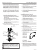
2 ft.
Min.
2 ft. Min.
X
12
H*
FP1971
Min chimney clearance
FP1971
Figure 35 -
Minimum Chimney Clearance
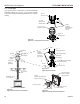
Horizontal Overhang
Vertical Wall
Termination
Vent
Storm Collar
Flashing
Concentric
Vent Pipe
1" Minimum Clearance to
Combustibles
Lowest
Discharge
Opening
Flat to 6/1 1.0
Over 6/1 to 7/1 1.5
Over 7/1 to 8/1 1.5
Over 8/1 to 9/1 .0
Over 9/1 to 10/1 .5
Over 10/1 to 11/1 3.5
Over 11/1 to 1/1 4.0
*H - Minimum height from roof to
lowest discharge opening of vent